ECD SYSTEM (w/ EGR Cooler), Diagnostic DTC:P245C, P245D
| DTC Code | DTC Name |
|---|---|
| P245C | EGR Cooler Bypass Control Circuit Low |
| P245D | EGR Cooler Bypass Control Circuit High |
DESCRIPTION
The No. 2 EGR valve (EGR cooler bypass valve) is installed on the opening of the EGR cooler. The ECM optimizes exhaust gas temperature and improves exhaust gas purification by performing the following: 1) using information from the crankshaft position sensor, engine coolant temperature sensor, load signals, etc.; 2) sending the negative pressure (applied to the diaphragm) through the VSV (for No. 2 EGR valve); and 3) opens and closes the switching valve.
This DTC is designed to detect an open or short in the VSV (for No. 2 EGR valve) circuit.
| DTC No. | DTC Detection Condition | Trouble Area |
|---|---|---|
| P245C | Open in VSV for No. 2 EGR valve circuit for 3 seconds (1 trip detection logic) |
|
| P245D | Short in VSV for No. 2 EGR valve circuit for 3 seconds (1 trip detection logic) |
|
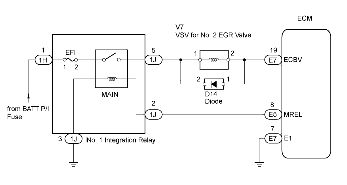
WIRING DIAGRAM
INSPECTION PROCEDURE
Note
After replacing the ECM, the new ECM needs registration Click here and initialization Click here.
Tech Tips
Read freeze frame data using the intelligent tester. Freeze frame data records the engine conditions when a malfunction is detected. When troubleshooting, freeze frame data can help determine if the vehicle was running or stopped, if the engine was warmed up or not, and other data from the time the malfunction occurred.
PROCEDURE
-
INSPECT NO. 2 VACUUM SWITCHING VALVE FOR NO. 2 EGR (RESISTANCE)
-
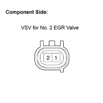
Disconnect the V7 VSV for No. 2 EGR valve connector.
-
Measure the resistance of the VSV for No. 2 EGR valve.
Standard resistance Tester Connection Condition Specified Condition 1 - 2 20°C (68°F) 37 to 44 Ω
NG 
REPLACE VSV FOR NO. 2 EGR VALVE Click here
OK 
-
-
INSPECT NO. 2 VACUUM SWITCHING VALVE FOR NO. 2 EGR (POWER SOURCE VOLTAGE)
-
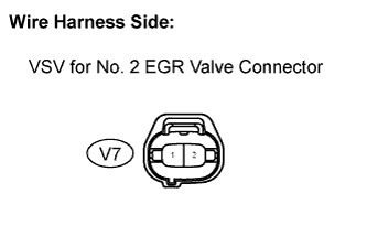
Disconnect the V7 VSV for No. 2 EGR valve connector.
-
Turn the ignition switch ON.
-
Measure the voltage of the wire harness side connector and body ground.
Standard voltage Tester Connection Specified Condition V7-1 - Body ground 11 to 14 V
NG 
CHECK HARNESS AND CONNECTOR (NO. 1 INTEGRATION RELAY - VSV FOR NO. 2 EGR VALVE) Click here
OK
-
-
CHECK HARNESS AND CONNECTOR (VSV FOR NO. 2 EGR VALVE - ECM)
-
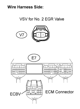
Disconnect the V7 VSV for No. 2 EGR valve connector.
-
Remove the E7 ECM connector.
-
Measure the resistance of the wire harness side connector.
Standard resistance (Check for open) Tester Connection Specified Condition V7-2 - ECBV (E7-19) Below 1 Ω Standard resistance (Check for short) Tester Connection Specified Condition V7-2 or ECBV (E7-19) - Body ground 10 kΩ or higher
NG
REPAIR OR REPLACE HARNESS OR CONNECTOR
OK 
REPLACE ECM Click here
-
-
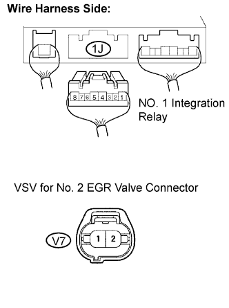
CHECK HARNESS AND CONNECTOR (NO. 1 INTEGRATION RELAY - VSV FOR NO. 2 EGR VALVE)
-
Remove the No. 1 integration relay from the engine room junction block Click here.
-
Disconnect the 1J No. 1 integration relay connector.
-
Disconnect the S7 VSV for No. 2 EGR valve connector.
-
Measure the resistance of the wire harness side connectors.
Standard resistance (Check for open) Tester Connection Specified Condition 1J-5 - S7-2 Below 1 Ω Standard resistance (Check for short) Tester Connection Specified Condition 1J-5 or S7-2 - Body ground 10 kΩ or higher
NG
REPAIR OR REPLACE HARNESS OR CONNECTOR
OK
INSPECT ECM POWER SOURCE CIRCUIT Click here
-