INTAKE MANIFOLD REMOVAL
CAUTION / NOTICE / HINT
CAUTION:
-
Orange wire harnesses and connectors indicate high-voltage circuits. To prevent electric shock, always follow the procedure described in the repair manual.
-
To prevent electric shock, wear insulated gloves when working on wire harnesses and components of the high voltage system.
Note
This procedure includes the removal of small-head bolts. Refer to Small-Head Bolts of Basic Repair Hint to identify the small-head bolts.
PROCEDURE
-
PRECAUTION
Note
After turning the engine switch off, waiting time may be required before disconnecting the cable from the negative (-) battery terminal. Therefore, make sure to read the disconnecting the cable from the negative (-) battery terminal notices before proceeding with work.
-
DISCHARGE FUEL SYSTEM PRESSURE
-
REMOVE COWL TOP VENTILATOR LOUVER SUB-ASSEMBLY
-
REMOVE INTAKE AIR SURGE TANK ASSEMBLY WITH INTERCOOLER
-
DISCONNECT FUEL TUBE SUB-ASSEMBLY
-
REMOVE FUEL TUBE SUB-ASSEMBLY
-
REMOVE FUEL TUBE SUB-ASSEMBLY
-
REMOVE FUEL HOSE PROTECTOR
-
REMOVE INTAKE MANIFOLD
-
REMOVE NO. 1 FUEL DELIVERY PIPE SUB-ASSEMBLY RH
-
REMOVE NO. 1 FUEL DELIVERY PIPE SUB-ASSEMBLY LH
-
REMOVE NO. 2 MANIFOLD STAY
-
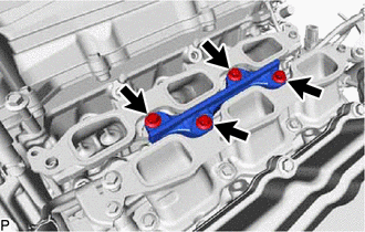
Remove the 4 bolts and No. 2 manifold stay from the lower intake manifold sub-assembly.
-
-
REMOVE FUEL VAPOR FEED PIPE SUB-ASSEMBLY
-
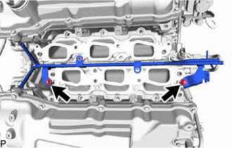
Remove the 2 bolts and fuel vapor feed pipe sub-assembly from the lower intake manifold sub-assembly.
-
-
REMOVE LOWER INTAKE MANIFOLD SUB-ASSEMBLY
-
for Bank 1:
-
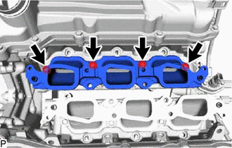
Remove the 4 bolts and lower intake manifold sub-assembly.
-
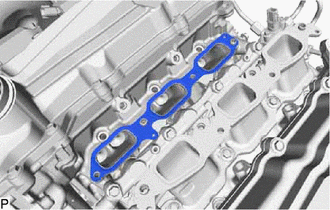
Remove the No. 1 intake manifold to head gasket.
-
-
for Bank 2:
-
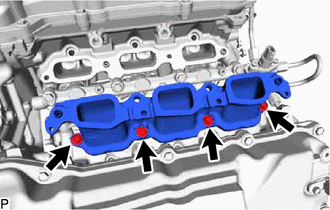
Remove the 4 bolts and lower intake manifold sub-assembly.
-
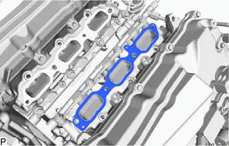
Remove the No. 1 intake manifold to head gasket.
-
-