CAMSHAFT POSITION SENSOR REMOVAL
CAUTION / NOTICE / HINT
The necessary procedures (adjustment, calibration, initialization or registration) that must be performed after parts are removed and installed, or replaced during VVT sensor removal/installation are shown below.
| Replaced Part or Performed Procedure | Necessary Procedure | Effect/Inoperative Function when Necessary Procedure not Performed | Link |
|---|---|---|---|
| Battery terminal is disconnected/reconnected | Memorize steering angle neutral point | LKA/LDA System | |
| Intelligent clearance sonar system*1 | |||
| Pre-crash safety system | |||
| Lighting system (EXT)
|
|||
| Adaptive high beam system | |||
| Drive the vehicle until stop and start control is permitted (approximately 15 to 60 minutes) | Stop and start system | ||
| Memorize steering angle neutral point | Parking Assist Monitor System (w/ Parallel Parking Assist Function) | ||
| Parking Assist Monitor System (w/o Parallel Parking Assist Function) | |||
| Panoramic view monitor system | |||
| Initialize back door lock | Power door lock control system | ||
| Reset back door close position | Power back door system | ||
|
Inspection After Repair |
|
Click here w/ Canister Pump Module Click here w/o Canister Pump Module |
*1: When performing learning using the GTS.
PROCEDURE
-
REMOVE INTAKE AIR SURGE TANK ASSEMBLY
-
REMOVE VVT SENSOR (for Intake Side of Bank 1)
-
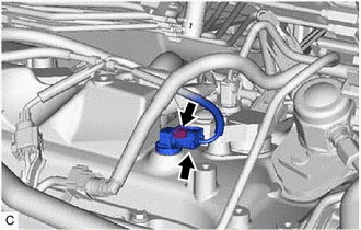
Disconnect the VVT sensor connector.
-
Remove the bolt and VVT sensor from the cylinder head cover sub-assembly.
Note
If the VVT sensor has been struck or dropped, replace it.
-
-
REMOVE VVT SENSOR (for Exhaust Side of Bank 1)
-
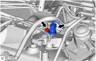
Disconnect the VVT sensor connector.
-
Remove the bolt and VVT sensor from the cylinder head cover sub-assembly.
Note
If the VVT sensor has been struck or dropped, replace it.
-
-
REMOVE VVT SENSOR (for Intake Side of Bank 2)
-
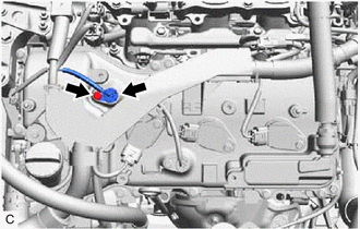
Disconnect the VVT sensor connector.
-
Remove the bolt and VVT sensor from the cylinder head cover sub-assembly LH.
Note
If the VVT sensor has been struck or dropped, replace it.
-
-
REMOVE VVT SENSOR (for Exhaust Side of Bank 2)
-
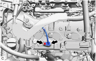
Disconnect the VVT sensor connector.
-
Remove the bolt and VVT sensor from the cylinder head cover sub-assembly LH.
Note
If the VVT sensor has been struck or dropped, replace it.
-