AIR CONDITIONING UNIT INSTALLATION

-
INSTALL AIR CONDITIONING RADIATOR ASSEMBLY
-
Install the air conditioning radiator assembly with the 3 screws.
-
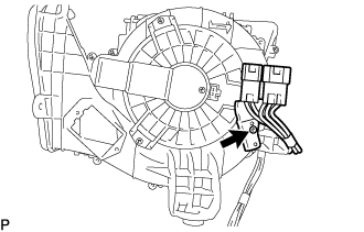
for LHD, w/ PTC:
-
Install the wire harness with the screw.
-
-
for RHD, w/ PTC:
-
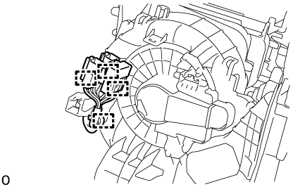
Attach the clamp.
-
-
-
INSTALL AIR DUCT NO.2
-
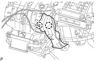
Engage the 2 claws to install the air duct No.2.
-
-
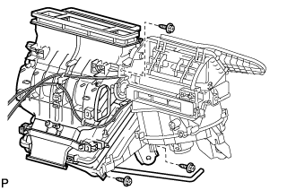
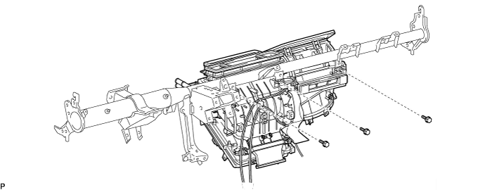
INSTALL AIR CONDITIONER UNIT ASSEMBLY
-
Install the air conditioner unit assembly with the 3 bolts.
-
-
INSTALL INSTRUMENT PANEL REINFORCEMENT ASSEMBLY
-
Driver seat:
-
Using a "Torx" socket wrench (T40), install the instrument panel reinforcement assembly with the 2 Torx bolts.
-
-
Passenger seat:
-
Using a hexagon wrench 12 mm, install the instrument panel reinforcement assembly with the 2 bolts.
- Torque:
- 6.0 N*m { 61 kgf*cm, 53 in.*lbf }
-
Using a "Torx" socket wrench (T40), install the instrument panel reinforcement assembly with the 2 "Torx" bolts.
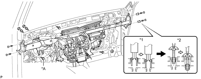
Text in Illustration *A for Manual Transmission - - *1 Collar *2 ''Torx'' Bolt - Torque:
- 20 N*m { 204 kgf*cm, 15 ft.*lbf }
-
-
Install the 2 bolts and nut. (AUTOMATIC TRANSMISSION)
-
Install the 3 bolts and nut. (MANUAL TRANSMISSION)
-
Install the 2 bolts and cap.
-
Attach the clamps and connectors.
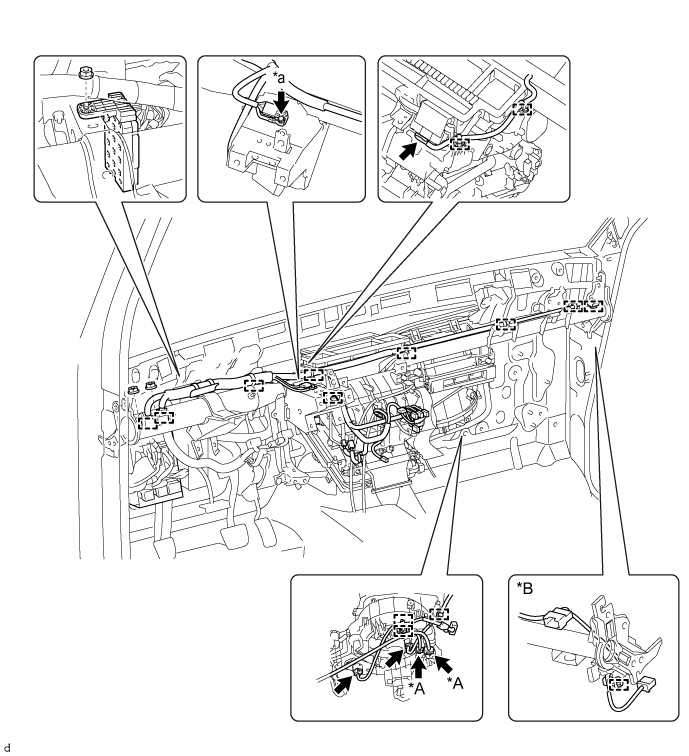
*A w/ PTC *B for Wide Body *a Ground Wire - - -
Install the bolt and nut.
- Torque:
- Ground Wire
- 8.4 N*m { 86 kgf*cm, 74 in.*lbf }
-
-
INSTALL INSTRUMENT PANEL TO FLOOR BRACE SUB-ASSEMBLY
-
CONNECT PARKING BRAKE CONTROL HANDLE SUB-ASSEMBLY
-
INSTALL AIR DUCT NO.1
-
INSTALL STEERING COLUMN ASSEMBLY
-
INSTALL INSTRUMENT PANEL ASSEMBLY
-
INSTALL HEATER WATER HOSE INLET A
-
INSTALL HEATER WATER HOSE OUTLET
-
INSTALL COOLER REFRIGERANT LIQUID PIPE B
-
Remove the attached vinyl tape from the pipe.
-
Sufficiently apply compressor oil to a new O-ring and the fitting surface of the cooler refrigerant liquid pipe B.
Compressor oil ND-OIL 8 or equivalent -
Install the O-ring on the cooler refrigerant liquid pipe B.
-
Install the cooler refrigerant liquid pipe B.
-
-
INSTALL COOLER REFRIGERANT SUCTION PIPE A
-
Remove the attached vinyl tape from the hose.
-
Sufficiently apply compressor oil to a new O-ring and the fitting surface of the cooler refrigerant suction pipe A.
Compressor oil ND-OIL 8 or equivalent -
Install the O-ring on the cooler refrigerant suction pipe A.
-
Move the hook connector in the direction indicated by the arrow in the illustration.
-
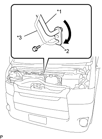
Text in Illustration *1 Cooler Refrigerant Suction Pipe A *2 Hook Connector *3 Cooler Refrigerant Liquid Insert the pipe joints into the fitting holes securely and tighten the bolt.
- Torque:
- 5.4 N*m { 55 kgf*cm, 48 in.*lbf }
-
-
INSTALL INTERCOOLER ASSEMBLY (w/ Intercooler)
-
for 1KD-FTV: Click here
-
for 2KD-FTV: Click here
-
for 1GD-FTV: Click here
-
-
REMOVE NO.1 ENGINE UNDER COVER (w/ Under Cover and Intercooler)
-
INSTALL WINDSHIELD WIPER MOTOR AND LINK ASSEMBLY
-
CONNECT CABLE TO NEGATIVE BATTERY TERMINAL
- Torque:
- 5.4 N*m { 55 kgf*cm, 48 in.*lbf }
Note
When disconnecting the cable, some systems need to be initialized after the cable is reconnected Click here.
-
ADD ENGINE COOLANT
-
for 1KD-FTV: Click here
-
for 2KD-FTV: Click here
-
for 1TR-FE: Click here
-
for 2TR-FE: Click here
-
for 5L-E: Click here
-
for 1GD-FTV: Click here
-
-
CHARGE REFRIGERANT
-
WARM UP ENGINE
-
CHECK FOR ENGINE COOLANT LEAKS
-
for 1KD-FTV: Click here
-
for 1TR-FE: Click here
-
for 1GD-FTV: Click here
-
-
INSPECT COOLING SYSTEM
-
for 2KD-FTV: Click here
-
for 2TR-FE: Click here
-
for 5L-E: Click here
-
-
CHECK FOR LEAKAGE OF REFRIGERANT