TURBOCHARGER REMOVAL

-
REMOVE NO. 1 ENGINE UNDER COVER (for Cold Area Specification Vehicles)
-
Remove the 4 bolts and No. 1 engine under cover.
-
-
REMOVE NO. 2 ENGINE UNDER COVER (for Cold Area Specification Vehicles)
-
Remove the 6 bolts and No. 2 engine under cover.
-
-
DRAIN ENGINE COOLANT
CAUTION:
Do not remove the radiator reservoir cap sub-assembly while the engine and radiator are still hot. Pressurized, hot engine coolant and steam may be released and cause serious burns.
-
Loosen the radiator drain cock plug.
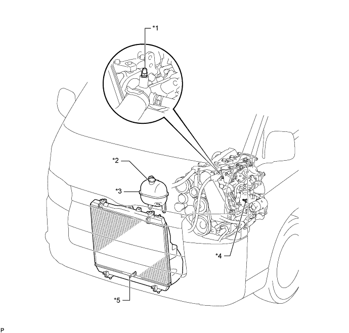
Text in Illustration *1 Bleeder Plug *2 Radiator Reservoir Cap Sub-assembly *3 Radiator Reservoir Assembly *4 Cylinder Block Drain Cock Plug *5 Radiator Drain Cock Plug - - -
Remove the radiator reservoir cap sub-assembly.
-
Loosen the cylinder block drain cock plug (on the engine oil cooler cover), and drain the engine coolant.
-
Tighten the radiator drain cock plug.
-
Tighten the cylinder block drain cock plug (on the engine oil cooler cover).
- Torque:
- 8.0 N*m { 82 kgf*cm, 71 in.*lbf }
-
-
DISCONNECT CABLE FROM NEGATIVE BATTERY TERMINAL
-
RECOVER REFRIGERANT FROM REFRIGERATION SYSTEM (w/ Air Conditioning System)
-
Start up the engine.
-
Turn the A/C switch on.
-
Operate the cooler compressor at an engine rpm of approximately 1,000 for 5 to 6 minutes to circulate the refrigerant and collect compressor oil remaining in each component into the cooler compressor as much as possible.
-
Stop the engine.
-
Using SST, let the refrigerant gas out.
- SST
- 07110-58060 ( 07117-58080, 07117-58090, 07117-78050, 07117-88060, 07117-88070, 07117-88080 )
-
-
REMOVE FRONT DOOR SCUFF PLATE RH
-
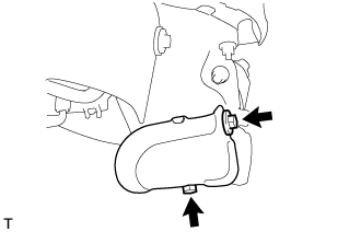
REMOVE FRONT SEAT ASSEMBLY RH
-
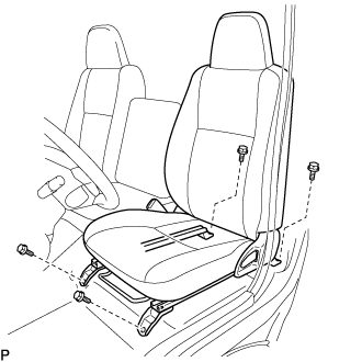
Move the front seat assembly fully forward.
-
Remove the 2 bolts on the rear side of the seat.
-
Move the front seat assembly to the rearmost position.
-
Remove the 2 bolts on the front side of the seat.
-
Move the front seat assembly to the center of the seat slide rail. Set the seatback in the upright position.
-
Disconnect the front seat inner belt assembly connector.
-
Remove the front seat assembly.
-
-
REMOVE ENGINE SERVICE HOLE SUB COVER SUB-ASSEMBLY
-
Roll up the carpet and remove the engine service hole sub cover.
-
-
REMOVE FENDER APRON MUDGUARD SEAL RH
-
REMOVE FAN AND GENERATOR V BELT (w/ Air Conditioning System)
-
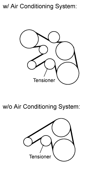
Remove the drive belt by rotating the tensioner pulley clockwise to loosen its tension with the pulley set bolt of the tensioner.
-
-
DISCONNECT NO. 1 COOLER REFRIGERANT DISCHARGE HOSE (w/ Air Conditioning System)
-
DISCONNECT NO. 1 COOLER REFRIGERANT SUCTION HOSE (w/ Air Conditioning System)
-
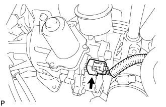
REMOVE COMPRESSOR AND MAGNETIC CLUTCH (w/ Air Conditioning System)
-
Disconnect the connector.
-
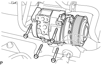
Remove the 4 bolts and compressor and magnetic clutch.
-
-
REMOVE FRONT EXHAUST PIPE ASSEMBLY (w/ DPF)
-
REMOVE FRONT EXHAUST PIPE ASSEMBLY (w/o DPF)
-
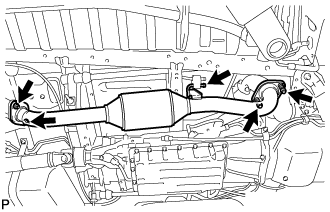
Remove the 2 bolts, 2 nuts and 2 compression springs.
-
Disconnect the front exhaust pipe assembly from the No. 4 exhaust pipe support.
-
Remove the 2 gaskets.
-
-
DISCONNECT TRANSMISSION CONTROL CABLE ASSEMBLY (for Manual Transmission)
-
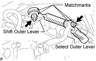
Put matchmarks on the transmission control cable assembly and the select outer lever.
-
Put matchmarks on the transmission control cable assembly and the shift outer lever.
-
Remove the nut and disconnect the transmission control cable assembly from the select outer lever.
-
Remove the nut and disconnect the transmission control cable assembly from the shift outer lever.
-
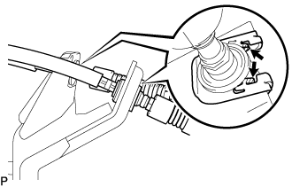
Using a screwdriver, disengage the claws of the 2 clips.
-
Remove the 2 transmission control cable assemblies and 2 clips from the No. 1 transmission control cable bracket.
-
-
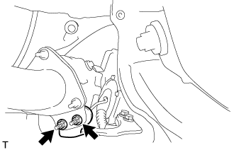
REMOVE NO. 1 TRANSMISSION CONTROL CABLE BRACKET (for Manual Transmission)
-
Remove the 2 bolts and No. 1 transmission control cable bracket.
-
-
REMOVE NO. 2 EXHAUST MANIFOLD HEAT INSULATOR (w/ DPF)
-
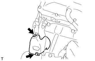
Remove the 2 bolts and No. 2 exhaust manifold heat insulator.
-
-
REMOVE NO. 3 EXHAUST MANIFOLD HEAT INSULATOR (w/ DPF)
-
Remove the 2 bolts and No. 3 exhaust manifold heat insulator.
-
-
REMOVE CATALYTIC WITH PIPE CONVERTER ASSEMBLY (w/ DPF)
-
Remove the 2 nuts from the catalytic with pipe converter assembly.
-
Remove the 3 nuts, catalytic with pipe converter assembly and gasket.
-
-
REMOVE NO. 2 FUEL PIPE CLAMP (w/ DPF)
-
Loosen the union bolt of the No. 3 fuel pipe.
-
Remove the 2 bolts and No. 2 fuel pipe clamp.
-
-
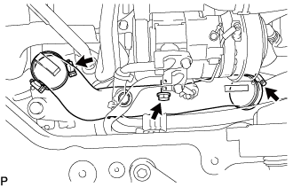
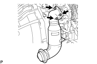
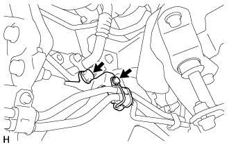
REMOVE TURBINE OUTLET ELBOW (w/ DPF)
-
Disconnect the fuel addition injector connector.
-
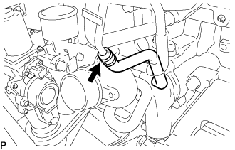
Slide the clamp and disconnect the No. 1 turbo water hose from No. 1 injector holder.
-
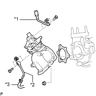
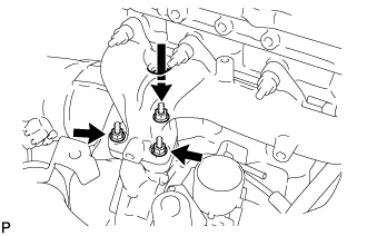
Text in Illustration *1 No. 3 Fuel Pipe *2 No. 4 Water By-pass Pipe *3 No. 13 Water By-pass Hose Remove the union bolt and gasket and disconnect the No. 3 fuel pipe from the No. 1 injector holder.
-
Remove the union bolt and gasket and disconnect the No. 4 water by-pass pipe from the No. 2 injector holder.
-
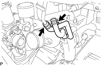
Slide the clamp and remove the No. 4 water by-pass pipe from the No. 13 water by-pass hose.
-
Remove the 3 nuts, turbine outlet elbow and gasket.
-
-
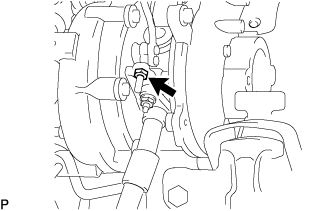
DISCONNECT NO. 1 AIR CLEANER HOSE
-
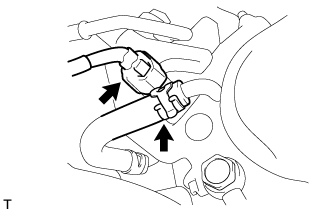
Pull the stopper upward and disconnect the No. 1 air cleaner hose from the compressor inlet elbow.
-
-
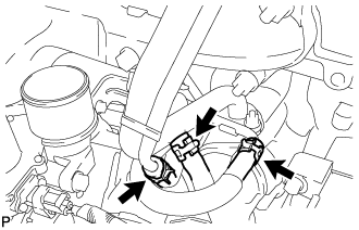
REMOVE AIR TUBE ASSEMBLY
-
Loosen the 2 hose clamps.
-
Remove the 2 bolts, air tube assembly and No. 1 air cleaner hose.
-
-
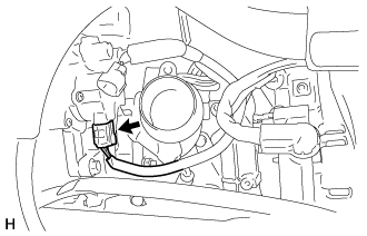
DISCONNECT TURBOCHARGER MOTOR CONNECTOR
-
REMOVE COMPRESSOR OUTLET ELBOW
-
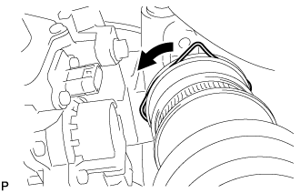
Loosen the 2 hose clamps and remove the bolt and compressor outlet elbow.
-
-
REMOVE NO. 1 COMPRESSOR MOUNTING BRACKET (w/ Air Conditioning System)
-
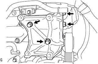
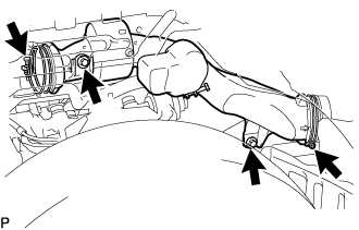
Remove the 4 bolts and No. 1 compressor mounting bracket.
-
-
REMOVE WIRE HARNESS CLAMP BRACKET
-
Detach the 3 clamps.
-
Remove the bolt and wire harness clamp bracket.
-
-
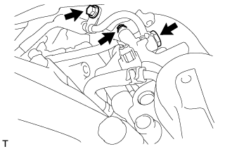
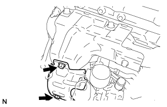
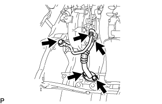
REMOVE VENTILATION PIPE
-
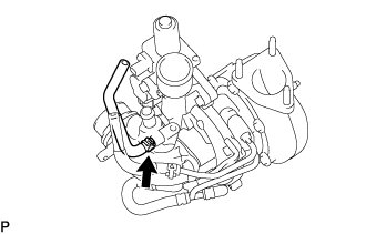
w/ DPF:
-
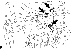
Remove the bolt and ventilation pipe.
-
Disconnect the 2 ventilation hoses.
-
-
w/o DPF:
-
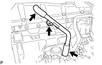
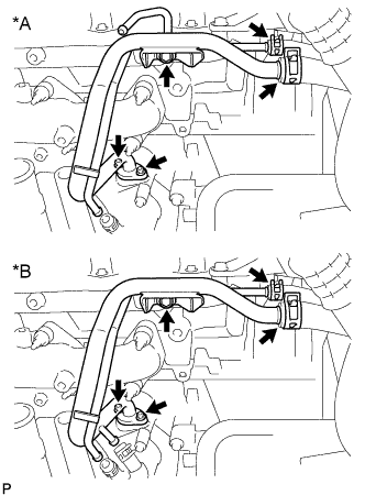
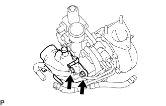
for Type A:
Slide the 2 clamps and remove the No. 14 water by-pass hose from the ventilation pipe and No. 2 water by-pass pipe.
-
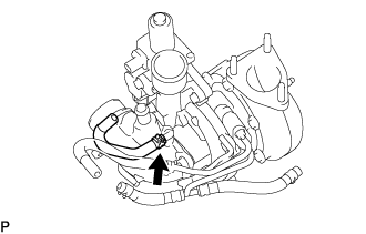
for Type A:
Slide the clamp and disconnect the No. 4 turbo water hose from the ventilation pipe.
-
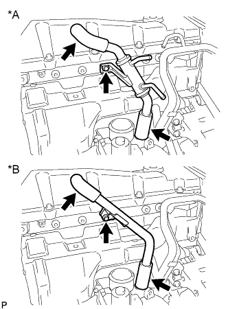
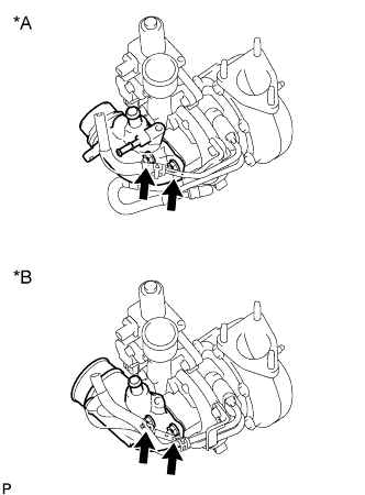
Text in Illustration *A for Type A *B for Type B Remove the bolt and ventilation pipe.
-
Disconnect the 2 ventilation hoses.
-
-
-
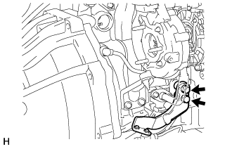
REMOVE TURBO INSULATOR
-
Remove the 2 bolts and turbo insulator.
-
-
REMOVE NO. 1 EXHAUST MANIFOLD HEAT INSULATOR
-
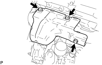
Remove the 3 bolts and No. 1 exhaust manifold heat insulator.
-
-
REMOVE TURBINE OUTLET ELBOW STAY
-
w/ DPF:
Remove the 2 bolts and turbine outlet elbow stay.
-
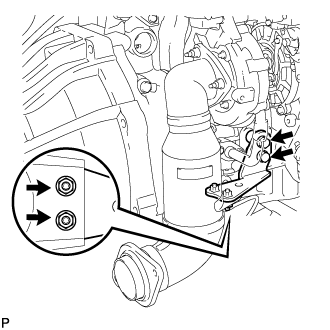
w/o DPF:
Remove the 2 bolts, 2 nuts and turbine outlet elbow stay.
-
-
REMOVE EXHAUST MANIFOLD CONVERTER SUB-ASSEMBLY (w/o DPF)
-
Remove the 3 nuts, exhaust manifold converter sub-assembly and gasket.
-
-
REMOVE TURBOCHARGER STAY
-
Remove the 2 bolts, nut and turbocharger stay.
-
-
REMOVE NO. 1 AUTOMATIC TRANSMISSION OIL COOLER TUBE CLAMP (for Automatic Transmission)
-
Remove the 2 bolts and No. 1 automatic transmission oil cooler tube clamp.
-
-
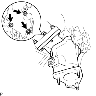
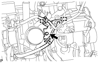
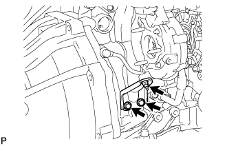
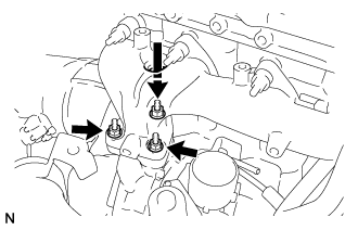
REMOVE TURBO OIL INLET PIPE SUB-ASSEMBLY
-
Remove the 2 bolts, 2 nuts and union bolt, and then remove the turbo oil inlet pipe sub-assembly and 3 gaskets.
Note
Do not loosen the nut as shown in the illustration. If the nut is mistakenly loosened, replace the turbocharger.
-
-
DISCONNECT TURBOCHARGER STROKE SENSOR CONNECTOR
-
REMOVE TURBOCHARGER
-
w/ DPF:
-
Slide the 3 clamps and disconnect the 3 turbo water hoses from the No. 5 water by-pass pipe sub-assembly and No. 2 water by-pass pipe.
-
Remove the 3 nuts and disconnect the turbocharger.
-
Temporarily place the turbocharger on the mounting bracket.
-
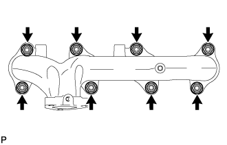
Remove the 8 nuts, 8 plate washers, 8 collars and exhaust manifold.
-
Remove the turbocharger and gasket.
-
-
w/o DPF:
-
Remove the 3 nuts and disconnect the turbocharger.
-
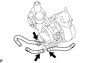
for Type A:
Slide the clamp and disconnect the No. 2 turbo water hose from the No. 2 water by-pass pipe.
-
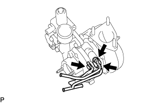
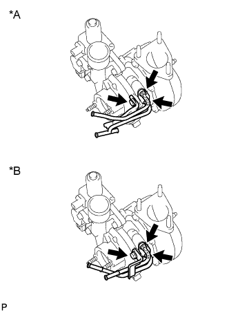
for Type B:
Slide the 2 clamps and disconnect the No. 1 turbo water hose and No. 2 turbo water hose from the No. 2 water by-pass pipe.
-
Text in Illustration *A for Type A *B for Type B Slide the 2 clamps and disconnect the 2 water hoses from the No. 2 water by-pass pipe.
-
Remove the bolt, 2 nuts, No. 2 water by-pass pipe and gasket.
-
Remove the turbocharger and gasket.
-
-
-
REMOVE COMPRESSOR INLET ELBOW
-
w/ DPF:
-
Slide the clamp and remove the No. 4 turbo water hose from the compressor inlet elbow.
-
Remove the 2 nuts, compressor inlet elbow and gasket.
-
-
w/o DPF:
-
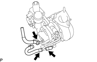
for Type A:
Slide the clamp and remove the No. 4 turbo water hose from the compressor inlet elbow.
-
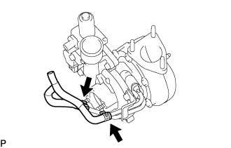
Text in Illustration *A for Type A *B for Type B Remove the 2 nuts, compressor inlet elbow and gasket.
-
-
-
REMOVE NO. 1 TURBO WATER PIPE SUB-ASSEMBLY
-
w/ DPF:
-
Slide the 3 clamps and remove the turbo water hose, No. 2 turbo water hose and No. 13 turbo water hose from the No. 1 turbo water pipe sub-assembly.
-
Remove the bolt, 2 nuts, No. 1 turbo water pipe and gasket.
-
-
w/o DPF:
-
for Type A:
Slide the 3 clamps and remove the No. 2 turbo water hose, No. 3 turbo water hose and plug from the No. 1 turbo water pipe sub-assembly.
-
for Type B:
Slide the 2 clamps and remove the No. 1 turbo water hose and No. 2 turbo water hose from the No. 1 turbo water pipe sub-assembly.
-
Text in Illustration *A for Type A *B for Type B Remove the bolt, 2 nuts, No. 1 turbo water pipe and gasket.
-
-