INTAKE MANIFOLD REMOVAL
CAUTION / NOTICE / HINT
The necessary procedures (adjustment, calibration, initialization or registration) that must be performed after parts are removed and installed, or replaced during intake manifold removal/installation are shown below.
| Replaced Part or Performed Procedure | Necessary Procedure | Effect/Inoperative Function when Necessary Procedure not Performed | Link |
|---|---|---|---|
| Battery terminal is disconnected/reconnected | Memorize steering angle neutral point | LKA/LDA System | |
| Pre-crash safety system | |||
| Lighting system (EXT)
|
|||
| Adaptive high beam system | |||
| Drive the vehicle until stop and start control is permitted (approximately 15 to 60 minutes) | Stop and start system | ||
| Memorize steering angle neutral point | Parking Assist Monitor System (w/ Parallel Parking Assist Function) | ||
| Parking Assist Monitor System (w/o Parallel Parking Assist Function) | |||
| Panoramic view monitor system | |||
| Initialize back door lock | Power door lock control system | ||
| Reset back door close position | Power back door system | ||
|
Inspection After Repair |
|
w/ Canister Pump Module: Click here w/o Canister Pump Module: Click here |
PROCEDURE
-
PRECAUTION
Note
After turning the engine switch off, waiting time may be required before disconnecting the cable from the negative (-) battery terminal. Therefore, make sure to read the disconnecting the cable from the negative (-) battery terminal notices before proceeding with work.
-
DISCHARGE FUEL SYSTEM PRESSURE
-
DISCONNECT CABLE FROM NEGATIVE BATTERY TERMINAL
Note
When disconnecting the cable, some systems need to be initialized after the cable is reconnected.
-
REMOVE THROTTLE BODY WITH MOTOR ASSEMBLY
-
REMOVE V-BANK COVER SUB-ASSEMBLY
-
DISCONNECT VENTILATION HOSE
-
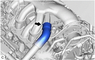
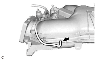
Slide the clip and disconnect the ventilation hose from the intake air surge tank assembly.
-
-
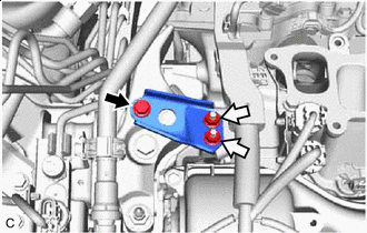
DISCONNECT PURGE VALVE (PURGE VSV)
-
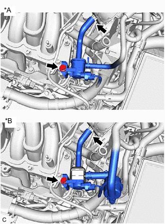
*A w/o Canister Pump Module *B w/ Canister Pump Module Disconnect the No. 1 fuel vapor feed hose from the intake air surge tank assembly.
-
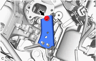
Remove the bolt and disconnect the purge valve (purge VSV) from the intake air surge tank assembly.
-
-
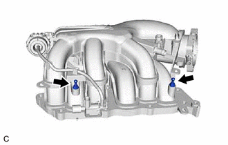
REMOVE NO. 2 SURGE TANK STAY
-
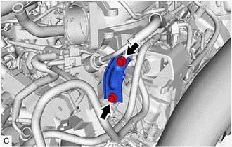
Remove the 2 bolts and No. 2 surge tank stay from the intake manifold and camshaft housing RH.
-
-
REMOVE INTAKE AIR SURGE TANK ASSEMBLY
-
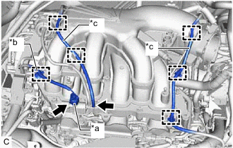
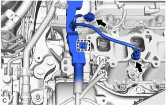
*a Vacuum Switching Valve (for ACIS) Connector *b Wire Harness Clamp *c Vacuum Hose Sub-assembly Disconnect the vacuum switching valve (for ACIS) connector.
-
Disengage the wire harness clamp from the intake air surge tank assembly.
-
Disengage the 5 clamps to disconnect the vacuum hose sub-assembly from the intake air surge tank assembly.
-
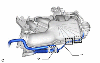
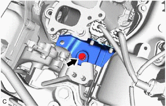
*1 Vacuum Hose Sub-assembly *2 No. 2 Air Tube Disengage the 2 clamps to disconnect the vacuum hose sub-assembly from the intake air surge tank assembly.
-
Disengage the clamp to disconnect the No. 2 air tube from the intake air surge tank assembly.
-

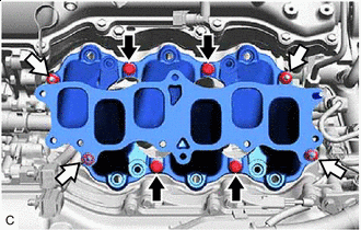
Bolt 
Nut Remove the 5 bolts, 2 nuts and intake air surge tank assembly from the intake manifold.
-
Disconnect the vacuum hose sub-assembly from the intake air surge tank assembly.
-
-
REMOVE AIR SURGE TANK TO INTAKE MANIFOLD GASKET
-
Remove the air surge tank to intake manifold gasket from the intake air surge tank assembly.
-
-
REMOVE NO. 1 V-BANK COVER BRACKET
Tech Tips
Perform this procedure only when replacement of the No. 1 V-bank cover bracket is necessary.
-
Remove the 2 No. 1 V-bank cover brackets from the intake air surge tank assembly.
-
-
REMOVE NO. 2 ENGINE MOUNTING STAY RH
-
Bolt Nut Remove the bolt, 2 nuts and No. 2 engine mounting stay RH from the engine mounting insulator sub-assembly RH.
-
Disengage the wire harness clamp from the wire harness clamp bracket.
-
Remove the bolt and disconnect the wire harness clamp bracket from the No. 2 engine mounting stay RH.
-
Remove the bolt and No. 2 engine mounting stay RH from the intake manifold and engine mounting insulator sub-assembly RH.
-
-
DISCONNECT FUEL TUBE SUB-ASSEMBLY
-
REMOVE FUEL DELIVERY PIPE SUB-ASSEMBLY
-
REMOVE NO. 1 DELIVERY PIPE SPACER
-
REMOVE INJECTOR VIBRATION INSULATOR
-
REMOVE INTAKE MANIFOLD
-
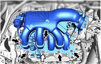
Bolt Nut Remove the 4 bolts, 4 nuts and intake manifold from the cylinder head sub-assembly.
-
-
REMOVE NO. 1 INTAKE MANIFOLD TO HEAD GASKET
-
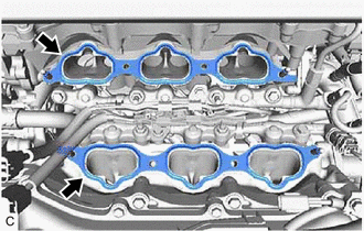
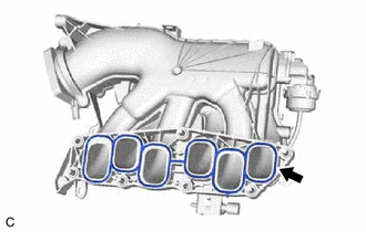
Remove the 2 No. 1 intake manifold to head gaskets from each cylinder head sub-assembly.
-
-
REMOVE STUD BOLT
Tech Tips
If a stud bolt is deformed or the threads are damaged, replace it.
-
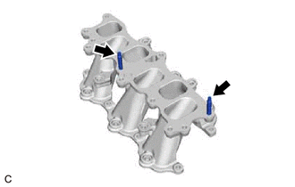
Using an E6 "TORX" socket wrench, remove the 2 stud bolts from the intake manifold.
-