ELECTRONIC SHIFT LEVER SYSTEM(for 8GR-FKS), Diagnostic DTC:U010387
| DTC Code | DTC Name |
|---|---|
| U010387 | Lost Communication with Gear Shift Control Module "A" Missing Message |
DESCRIPTION
The shift control ECU transmits and receives signals via CAN communication to and from the ECM.
| DTC No. | Detection Item | DTC Detection Condition | Trouble Area | MIL | Warning Indicate |
|---|---|---|---|---|---|
| U010387 | Lost Communication with Gear Shift Control Module "A" Missing Message | 3 seconds elapse after turning engine switch on (IG) with battery voltage 10 V or higher and a CAN communication malfunction (battery local bus) between ECM occurs continuously for 1 second or more. (1 trip detection logic) |
|
Does not come on |
|
CONFIRMATION DRIVING PATTERN
Tech Tips
After repair has been completed, clear the DTC and then check that the vehicle has returned to normal by performing the All Readiness check procedure.
-
Turn the engine switch on (IG) and wait for 2 minutes or more.
WIRING DIAGRAM
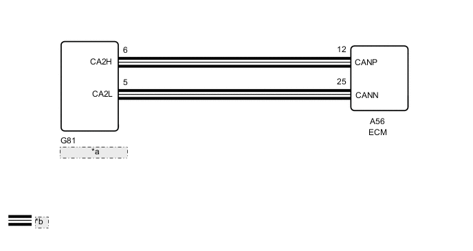
| *a | Shift Control ECU |
| *b | CAN Communication Line |
CAUTION / NOTICE / HINT
Note
-
After turning the engine switch off, waiting time may be required before disconnecting the cable from the negative (-) battery terminal. Therefore, make sure to read the disconnecting the cable from the negative (-) battery terminal notices before proceeding with work.
-
The vehicle is equipped with a sub-battery. Therefore, ensure there is no power being supplied to the vehicle when disconnecting or reconnecting the connector of the shift control ECU and when removing or installing the shift control ECU.
PROCEDURE
-
CHECK DTC OUTPUT (HEALTH CHECK)
-
Connect the GTS to the DLC3.
-
Turn the engine switch on (IG).
-
Enter the following menus: Health Check.
-
Check for DTCs.
Result Result Proceed to DTC P176D12 does not output. A DTC P176D12 is output. B -
Turn the engine switch off.
B 
GO TO DTC CHART (P176D12) Click here
A 
-
-
CHECK CONNECTOR CONNECTION CONDITION (SHIFT CONTROL ECU CONNECTOR)
-
Check the connector connections and contact pressure of the relevant terminals for the shift control ECU connectors.
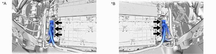
*A for LHD *B for RHD OK The connectors are connected securely and there are no contact pressure problems. Result Proceed to OK NG
NG
CONNECT SECURELY
OK
-
-
CHECK HARNESS AND CONNECTOR (SHIFT CONTROL ECU - ECM)
-
Disconnect the G81 shift control ECU connector.
-
Disconnect the A56 ECM connector.
-
Measure the resistance according to the value(s) in the table below.
Standard Resistance (Check for Open) Tester Connection Switch Condition Specified Condition G81-6(CA2H) - A56-12(CANP) Engine switch off Below 1 Ω G81-5(CA2L) - A56-25(CANN) Engine switch off Below 1 Ω Standard Resistance (Check for Short) Tester Connection Switch Condition Specified Condition G81-6(CA2H) or A56-12(CANP) - Body ground and other terminals Engine switch off 10 kΩ or higher G81-5(CA2L) or A56-25(CANN) - Body ground and other terminals Engine switch off 10 kΩ or higher -
Reconnect the A56 ECM connector.
-
Reconnect the G81 shift control ECU connector.
Result Proceed to OK NG
NG
REPAIR OR REPLACE HARNESS OR CONNECTOR
OK
-
-
CHECK ECM
-
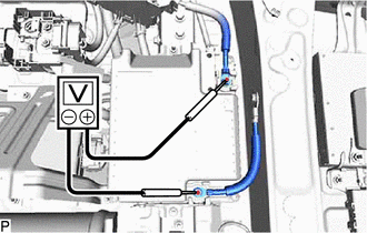
Check that the voltage between the terminals of the sub-battery module assembly is 0 V.
-
Disconnect the cable from the negative (-) battery terminal.
-
Disconnect the G81 shift control ECU connector.
-
Measure the resistance according to the value(s) in the table below.
Standard Resistance Tester Connection Condition Specified Condition G81-6(CA2H) - G81-5(CA2L) 20°C (68°F) 108 to 132 kΩ -
Reconnect the G81 shift control ECU connector.
-
Connect the cable to the negative (-) battery terminal.
Result Proceed to OK NG
OK
REPLACE SHIFT CONTROL ECU Click here
NG
REPLACE ECM Click here
-