BRAKE PEDAL(w/o Vacuum Brake Booster) REMOVAL
CAUTION / NOTICE / HINT
The necessary procedures (adjustment, calibration, initialization, or registration) that must be performed after parts are removed, installed, or replaced during brake pedal support assembly removal/installation are shown below.
| Replaced Part or Performed Procedure | Necessary Procedure | Effect/Inoperative Function when Necessary Procedure not Performed | Link |
|---|---|---|---|
| Battery terminal is disconnected/reconnected | Drive the vehicle until stop and start control is permitted (approximately 5 to 60 minutes) | Stop and start system | for 8GR-FKS: Click here for V35A-FTS: Click here |
| Memorize steering angle neutral point | LKA/LDA system | ||
| Parking support brake system* | |||
| Pre-collision system | |||
| Adaptive high beam system | |||
Lighting system (EXT) |
|||
| Variable gear ratio steering system | |||
| Parking assist monitor system | |||
| Panoramic view monitor system | |||
| Initialize rear door sunshade system | Rear door sunshade system | ||
| Initialize power trunk lid system | Power trunk lid system | ||
Electronically Controlled Brake System (w/o Vacuum Brake Booster): |
|
|
Click here Click here
Note
While the battery is connected, even if the engine switch is off, the brake control system activates when the brake pedal is depressed or the door courtesy switch is turned on. Therefore, even if only brake pads are to be removed and installed, be sure to remove the brake booster pump connectors before beginning work.
PROCEDURE
-
REMOVE STEERING COLUMN ASSEMBLY
-
DISCONNECT BRAKE PEDAL SUPPORT ASSEMBLY
-
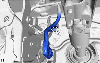
Disconnect the wire harness clamp from the brake pedal support assembly.
-
Remove the bolt and disconnect the brake pedal support assembly from the instrument panel reinforcement assembly.
-
-
REMOVE INSTRUMENT PANEL REINFORCEMENT ASSEMBLY
-
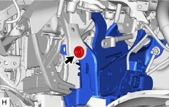
REMOVE BRAKE PEDAL STROKE SENSOR ASSEMBLY
-
REMOVE BRAKE PEDAL RETURN SPRING
-
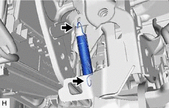
Remove the brake pedal return spring from the brake pedal support assembly.
-
-
REMOVE STOP LIGHT SWITCH ASSEMBLY
-
REMOVE STOP LIGHT SWITCH MOUNTING ADJUSTER
-
REMOVE PUSH ROD PIN
-
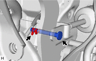
Remove the clip and push rod pin.
-
-
REMOVE BRAKE PEDAL SUPPORT ASSEMBLY
-
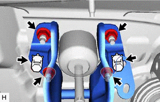
Remove the 2 clips from the brake pedal support assembly.
-
Remove the 4 nuts and brake pedal support assembly.
-
-
REMOVE BRAKE PEDAL PAD
-
Remove the brake pedal pad from the brake pedal support assembly.
-