CAMSHAFT INSTALLATION

CAUTION / NOTICE / HINT
Note
This procedure includes the installation of small-head bolts. Refer to Small-Head Bolts of Basic Repair Hint to identify the small-head bolts.
Tech Tips
Perform "Inspection After Repairs" after replacing the intake camshaft sub-assembly RH, exhaust camshaft sub-assembly RH, intake camshaft sub-assembly LH, exhaust camshaft sub-assembly LH, camshaft timing gear assembly or camshaft timing exhaust gear assembly.
-
w/ Canister Pump Module:
-
w/o Canister Pump Module:
PROCEDURE
-
SET NO. 1 CYLINDER TO TDC/COMPRESSION (for Bank 2)
-
INSTALL CAMSHAFT TIMING INTAKE GEAR ASSEMBLY LH
Tech Tips
Perform "Inspection After Repairs" after replacing the camshaft timing gear assembly LH.
-
w/ Canister Pump Module:
-
w/o Canister Pump Module:
-
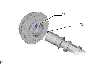
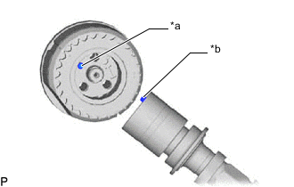
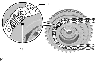
*a Pin Hole *b Straight Pin Put the camshaft timing gear assembly and camshaft together by aligning the pin hole and straight pin.
-
Temporarily install the camshaft timing gear bolt.
-

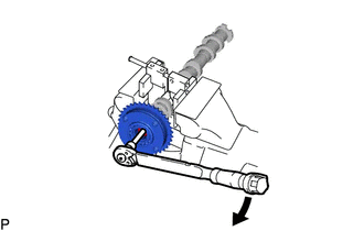
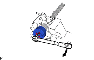
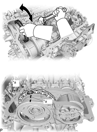
*a Hexagonal Portion Using SST, grip the hexagonal portion, and then secure SST and intake camshaft sub-assembly LH in a vise as shown in the illustration.
Note
-
Do not damage the intake camshaft sub-assembly LH.
-
Never grip areas other than the hexagonal portion, as this may cause damage.
-
-
Using a 10 mm bi-hexagonal wrench, install the camshaft timing gear assembly with the bolt.
- Torque:
- 86 N*m { 877 kgf*cm, 63 ft.*lbf }
-
-
INSTALL INTAKE CAMSHAFT SUB-ASSEMBLY LH
Tech Tips
Perform "Inspection After Repairs" after replacing the intake camshaft sub-assembly LH.
-
w/ Canister Pump Module:
-
w/o Canister Pump Module:
-
Clean the camshaft housing LH and camshaft journals and apply engine oil to them.
-
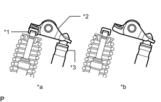
*1 Valve Stem Cap *2 No. 1 Valve Rocker Arm *3 Valve Lash Adjuster Assembly *a CORRECT *b INCORRECT Make sure that the No. 1 valve rocker arm sub-assembly is installed as shown in the illustration.
-
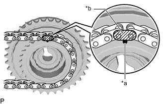
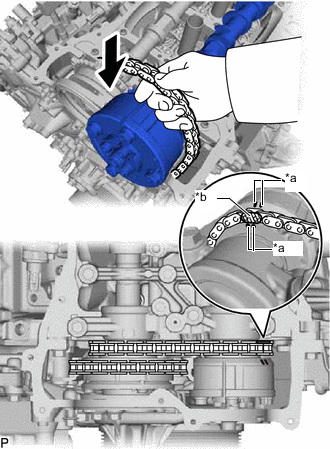
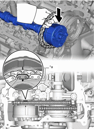
*a Timing Mark *b Mark Plate (Pink) Align the mark plate (Pink) with the timing mark of the camshaft timing gear assembly as shown in the illustration and install the No. 2 chain sub-assembly to the camshaft timing gear assembly.
-
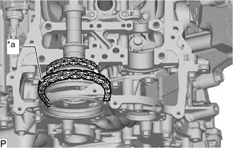
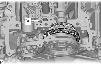
*a Place on camshaft timing gear assembly Install the No. 1 chain sub-assembly to the camshaft timing gear assembly, and then set the camshaft timing gear assembly to the camshaft housing LH.
Tech Tips
-
Place the No. 1 chain sub-assembly on the camshaft timing gear but do not engage the teeth of the sprocket and the No. 1 chain sub-assembly.
-
Install the camshaft timing gear so that the timing mark is facing upward.
-
-
-
INSTALL CAMSHAFT TIMING EXHAUST GEAR ASSEMBLY LH
Tech Tips
Perform "Inspection After Repairs" after replacing the camshaft timing exhaust gear assembly LH.
-
w/ Canister Pump Module:
-
w/o Canister Pump Module:
-
*a Pin Hole *b Straight Pin Align and fit the knock pin of the No. 2 camshaft to the knock pin hole of the camshaft timing exhaust gear assembly LH.
-
Temporarily install the bolt.
-

*a Hexagonal Portion Using SST, grip the hexagonal portion, and then secure SST and intake camshaft sub-assembly LH in a vise as shown in the illustration.
Note
-
Do not damage the intake camshaft sub-assembly LH.
-
Never grip areas other than the hexagonal portion, as this may cause damage.
-
-
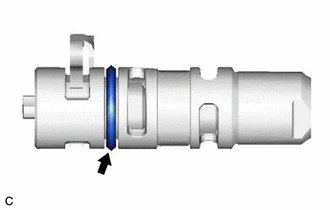
Apply a light coat of engine oil to the O-ring of the camshaft timing oil control valve assembly (exhaust camshaft timing gear bolt assembly).
Note
If reusing the camshaft timing oil control valve assembly (exhaust camshaft timing gear bolt assembly), be sure to inspect the O-ring.
-
Temporarily install the camshaft timing oil control valve assembly (exhaust camshaft timing gear bolt assembly) to the camshaft timing exhaust gear assembly.
Note
If the camshaft timing oil control valve assembly (exhaust camshaft timing gear bolt assembly) has been struck or dropped, replace it.
-
Using a 5 mm hexagon socket wrench, install the camshaft timing exhaust gear assembly with the 3 bolts and install the camshaft timing oil control valve assembly (exhaust camshaft timing gear bolt assembly).
- Torque:
- 19 N*m { 194 kgf*cm, 14 ft.*lbf }
-
-
INSTALL EXHAUST CAMSHAFT SUB-ASSEMBLY LH
Tech Tips
Perform "Inspection After Repairs" after replacing the exhaust camshaft sub-assembly LH.
-
w/ Canister Pump Module:
-
w/o Canister Pump Module:
-
Clean the camshaft housing LH and camshaft journals and apply engine oil to them.
-
*1 Valve Stem Cap *2 No. 1 Valve Rocker Arm *3 Valve Lash Adjuster Assembly *a CORRECT *b INCORRECT Make sure that the No. 1 valve rocker arm sub-assembly is installed as shown in the illustration.
-
*a Timing Mark *b Mark Plate (Pink) Align the mark plate (Pink) with the timing mark of the camshaft timing exhaust gear assembly as shown in the illustration and install the No. 2 chain sub-assembly to the exhaust camshaft sub-assembly LH.
-
Set the exhaust camshaft sub-assembly LH to the camshaft housing LH.
-
-
INSTALL CAMSHAFT BEARING CAP (for Bank 2)
-
Clean the camshaft bearing caps and apply engine oil to them.
-
Remove the bolt and washer (No. 5 camshaft bearing cap side) used to temporarily install the camshaft housing.
Note
Do not remove the bolt and washer for temporarily installing the camshaft housing other than those on the No. 5 camshaft bearing cap.
-
Temporarily install the No. 5 camshaft bearing cap.
Note
Hold the chain plunger of the No. 3 chain tensioner assembly and insert the No. 5 camshaft bearing cap through the gap in the No. 3 chain tensioner assembly and No. 2 chain sub-assembly to install it.
-
Remove the bolt and washer (No. 8 camshaft bearing cap and No. 9 camshaft bearing cap side) used to temporarily install the camshaft housing.
Note
Do not remove the bolt and washer for temporarily installing the camshaft housing other than those on the No. 8 camshaft bearing cap and No. 9 camshaft bearing cap.
-
Temporarily install the No. 8 camshaft bearing cap, No. 9 camshaft bearing cap and fuel pump lifter housing LH.
-
Remove the bolt and washer (No. 7 camshaft bearing cap side) used to temporarily install the camshaft housing.
Note
Do not remove the bolt and washer for temporarily installing the camshaft housing other than those on the No. 7 camshaft bearing cap.
-
Temporarily install the No. 6 camshaft bearing cap and No. 7 camshaft bearing cap.
-
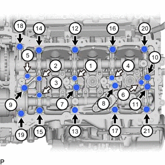

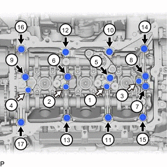
Bolt A 
Bolt B Tighten the bearing caps and fuel pump lifter housing LH with the bolts in the order shown in the illustration.
- Torque:
- Bolt A
- 28 N*m { 286 kgf*cm, 21 ft.*lbf }
- Bolt B
- 16 N*m { 163 kgf*cm, 12 ft.*lbf }
Note
-
Be sure to follow the numerical order when performing this procedure.
-
Do not drop replacement bolts and washers into the cylinder head sub-assembly.
-
Check the torque of each bolt again.
-
-
CONNECT NO. 1 CHAIN SUB-ASSEMBLY (for Bank 2)
-
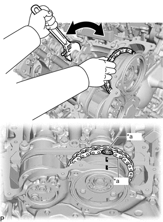
*a Paint Mark Align the paint marks on the camshaft timing gear assembly and chain sub-assembly and install the chain sub-assembly to the camshaft timing gear assembly.
Tech Tips
If the paint marks are not aligned, align them by turning the camshaft slightly.
-
-
INSTALL NO. 1 CHAIN TENSIONER ASSEMBLY (for Bank 2)
-
SET NO. 1 CYLINDER TO TDC/COMPRESSION (for Bank 1)
-
INSTALL CAMSHAFT TIMING INTAKE GEAR ASSEMBLY RH
Tech Tips
Perform "Inspection After Repairs" after replacing camshaft timing intake gear assembly RH.
-
w/ Canister Pump Module:
-
w/o Canister Pump Module:
-
*a Pin Hole *b Straight Pin Put the camshaft timing gear assembly and camshaft together by aligning the pin hole and straight pin.
-
Temporarily install the camshaft timing gear bolt.
-
*a Hexagonal Portion Using SST, grip the hexagonal portion, and then secure SST and intake camshaft sub-assembly RH in a vise as shown in the illustration.
Note
-
Do not damage the intake camshaft sub-assembly RH.
-
Never grip areas other than the hexagonal portion, as this may cause damage.
-
-
Using a 10 mm bi-hexagonal wrench, install the camshaft timing intake gear assembly RH with the bolt.
- Torque:
- 86 N*m { 877 kgf*cm, 63 ft.*lbf }
-
-
INSTALL INTAKE CAMSHAFT SUB-ASSEMBLY RH
Tech Tips
Perform "Inspection After Repairs" after replacing the intake camshaft sub-assembly RH.
-
w/ Canister Pump Module:
-
w/o Canister Pump Module:
-
Clean the camshaft housing RH and camshaft journals and apply engine oil to them.
-
*1 Valve Stem Cap *2 No. 1 Valve Rocker Arm *3 Valve Lash Adjuster Assembly *a CORRECT *b INCORRECT Make sure that the No. 1 valve rocker arm sub-assembly is installed as shown in the illustration.
-
*a Timing Mark *b Mark Plate (Pink) Align the mark plate (Pink) with the timing mark of the camshaft timing gear assembly as shown in the illustration and install the No. 2 chain sub-assembly to the camshaft timing intake gear assembly RH.
-
*a Place on camshaft timing gear Install the No. 1 chain sub-assembly to the camshaft timing gear assembly, and then set the camshaft timing gear assembly to the camshaft housing RH.
Tech Tips
-
Place the No. 1 chain sub-assembly on the camshaft timing gear assembly but do not engage the teeth of the sprocket and the chain sub-assembly.
-
Install the camshaft timing gear assembly so that the timing mark is facing upward.
-
-
-
INSTALL CAMSHAFT TIMING EXHAUST GEAR ASSEMBLY RH
Tech Tips
Perform "Inspection After Repairs" after replacing the camshaft timing exhaust gear assembly RH.
-
w/ Canister Pump Module:
-
w/o Canister Pump Module:
-
*a Pin Hole *b Straight Pin Align and fit the knock pin of the No. 2 camshaft to the knock pin hole of the camshaft timing exhaust gear assembly RH.
-
Temporarily install the bolt.
-
*a Hexagonal Portion Using SST, grip the hexagonal portion, and then secure SST and exhaust camshaft sub-assembly RH in a vise as shown in the illustration.
Note
-
Do not damage the exhaust camshaft sub-assembly RH.
-
Never grip areas other than the hexagonal portion, as this may cause damage.
-
-
Apply a light coat of engine oil to the O-ring of the camshaft timing oil control valve assembly (exhaust camshaft timing gear bolt assembly).
Note
If reusing the camshaft timing oil control valve assembly (exhaust camshaft timing gear bolt assembly), be sure to inspect the O-ring.
-
Temporarily install the camshaft timing oil control valve assembly (exhaust camshaft timing gear bolt assembly) to the camshaft timing exhaust gear assembly.
Note
If the camshaft timing oil control valve assembly (exhaust camshaft timing gear bolt assembly) has been struck or dropped, replace it.
-
Using a 5 mm hexagon socket wrench, install the camshaft timing exhaust gear assembly with the 3 bolts and install the camshaft timing oil control valve assembly (exhaust camshaft timing gear bolt assembly).
- Torque:
- 19 N*m { 194 kgf*cm, 14 ft.*lbf }
-
-
INSTALL EXHAUST CAMSHAFT SUB-ASSEMBLY RH
Tech Tips
Perform "Inspection After Repairs" after replacing the exhaust camshaft sub-assembly RH.
-
w/ Canister Pump Module:
-
w/o Canister Pump Module:
-
Clean the camshaft housing RH and camshaft journals and apply engine oil to them.
-
*1 Valve Stem Cap *2 No. 1 Valve Rocker Arm *3 Valve Lash Adjuster Assembly *a CORRECT *b INCORRECT Make sure that the No. 1 valve rocker arm sub-assembly is installed as shown in the illustration.
-
*a Timing Mark *b Mark Plate (Pink) Align the mark plate (Pink) with the timing mark of the camshaft timing exhaust gear assembly as shown in the illustration and install the No. 2 chain sub-assembly to the camshaft timing exhaust gear assembly.
-
Set the camshaft timing exhaust gear assembly to the camshaft housing RH.
-
-
INSTALL CAMSHAFT BEARING CAP (for Bank 1)
-
Clean the camshaft bearing caps and apply engine oil to them.
-
Remove the bolt and washer (No. 1 camshaft bearing cap side) used to temporarily install the camshaft housing.
Note
Do not remove the bolt and washer for temporarily installing the camshaft housing other than those on the No. 1 camshaft bearing cap.
-
Temporarily install the No. 1 camshaft bearing cap.
Note
Hold the chain plunger of the No. 2 chain tensioner assembly and insert the No. 1 camshaft bearing cap through the gap in the No. 2 chain tensioner assembly and No. 2 chain sub-assembly to install it.
-
Remove the bolt and washer (No. 3 camshaft bearing cap and No. 4 camshaft bearing cap side) used to temporarily install the camshaft housing.
Note
Do not remove the bolt and washer for temporarily installing the camshaft housing other than those on the No. 3 camshaft bearing cap and No. 4 camshaft bearing cap.
-
Temporarily install the No. 3 camshaft bearing cap, No. 4 camshaft bearing cap and fuel pump lifter housing RH.
-
Bolt A Bolt B Tighten the bearing caps and fuel pump lifter housing RH with the bolts in the order shown in the illustration.
- Torque:
- Bolt A
- 28 N*m { 286 kgf*cm, 21 ft.*lbf }
- Bolt B
- 16 N*m { 163 kgf*cm, 12 ft.*lbf }
Note
-
Be sure to follow the numerical order when performing this procedure.
-
Do not drop replacement bolts and washers into the cylinder head sub-assembly.
-
Check the torque of each bolt again.
-
-
CONNECT NO. 1 CHAIN SUB-ASSEMBLY (for Bank 1)
-
*a Paint Mark Align the paint marks on the camshaft timing gear assembly and chain sub-assembly and install the chain sub-assembly to the camshaft timing gear assembly.
Tech Tips
If the paint marks are not aligned, align them by turning the camshaft slightly.
-
-
INSTALL NO. 1 CHAIN TENSIONER ASSEMBLY
-
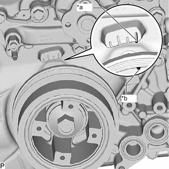
*a Timing Mark "0" *b Timing Mark (Groove) Turn the crankshaft counterclockwise 30° past the "0" timing mark, and then turn it clockwise to align the notch with the "0" timing mark.
-
Turn the crankshaft slightly to eliminate the slack in the chain sub-assembly.
Tech Tips
Make sure there is some slack in the chain around the area where the No. 1 chain tensioner assembly is installed.
-
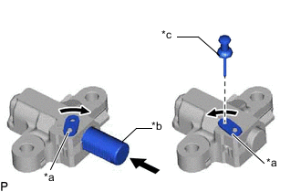
*a Stopper Plate *b Plunger *c Pin While turning the stopper plate of the tensioner clockwise, push in the plunger of the No. 1 chain tensioner assembly as shown in the illustration.
-
While turning the stopper plate of the No. 1 chain tensioner assembly counterclockwise, insert a pin of 1.27 mm (0.0500 in.) into the holes in the stopper plate and No. 1 chain tensioner assembly to fix the stopper plate in place.
-
Install the No. 1 chain tensioner assembly with the 2 bolts.
- Torque:
- 21 N*m { 214 kgf*cm, 15 ft.*lbf }
-
Remove the pin from the No. 1 chain tensioner assembly.
-
-
INSPECT VALVE TIMING
-
*a Timing Mark "0" *b Timing Mark (Groove) Turn the crankshaft until the timing mark (groove) of the crankshaft pulley assembly and the timing mark "0" of the timing chain cover assembly are aligned.
-
Check the camshaft timing marks.
Note
-
Check each timing mark from a viewpoint directly in line with the center of the camshaft and the timing mark on each camshaft timing gear assembly.
-
If the timing marks are checked from any other viewpoint, the valve timing may appear misaligned.
-
-
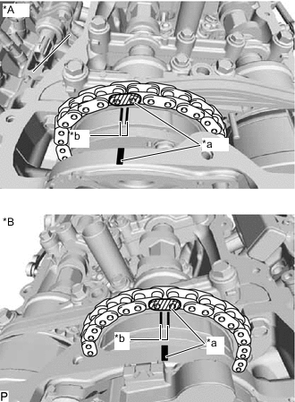
*A for Bank 2 *B for Bank 1 *a Paint Mark *b Timing Mark (Groove) Check that each camshaft timing mark is positioned as shown in the illustration.
-
If the valve timing is misaligned, reinstall the timing chain sub-assembly.
-
-
INSTALL TIMING CHAIN COVER PLATE
-
Install a new gasket and the timing chain cover plate with the 4 bolts.
- Torque:
- 10 N*m { 102 kgf*cm, 7 ft.*lbf }
-
-
INSTALL VACUUM PUMP ASSEMBLY
-
INSTALL CRANKSHAFT DAMPER SUB-ASSEMBLY
-
CONNECT CABLE TO NEGATIVE BATTERY TERMINAL
-
Connect the cable to the negative battery terminal.
- Torque:
- 6.5 N*m { 66 kgf*cm, 58 in.*lbf }
Note
When disconnecting the cable, some systems need to be initialized after the cable is reconnected.
-
-
INSTALL TOOL BOX
-
INSTALL LUGGAGE COMPARTMENT MAT SUB-ASSEMBLY
-
ADD ENGINE COOLANT
-
INSPECT FOR COOLANT LEAK
-
INSPECT IGNITION TIMING