ENGINE ASSEMBLY INSTALLATION
PROCEDURE
-
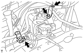
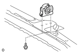
INSTALL ENGINE MOUNTING INSULATOR SUB-ASSEMBLY LH
Tech Tips
Perform this procedure only when replacement of the engine mounting insulator is necessary.
-
Install the engine mounting insulator with the 4 bolts.
- Torque:
- 95 N*m { 969 kgf*cm, 70 ft.*lbf }
-
-
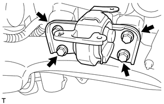
INSTALL ENGINE MOUNTING INSULATOR SUB-ASSEMBLY RH
Tech Tips
Perform this procedure only when replacement of the engine mounting insulator is necessary.
-
Install the engine mounting insulator with the 3 bolts.
- Torque:
- 95 N*m { 969 kgf*cm, 70 ft.*lbf }
-
Install the 2 cooler brackets with the 2 bolts and nut.
- Torque:
- 9.8 N*m { 100 kgf*cm, 87 in.*lbf }
-
Connect the cooler pipe clamp.
-
-
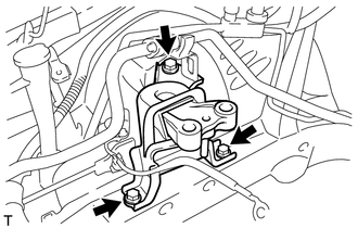
INSTALL REAR ENGINE MOUNTING INSULATOR
Tech Tips
Perform this procedure only when replacement of the engine mounting insulator is necessary.
-
Install the engine mounting insulator with the 2 bolts and 2 nuts.
- Torque:
- 95 N*m { 969 kgf*cm, 70 ft.*lbf }
-
-
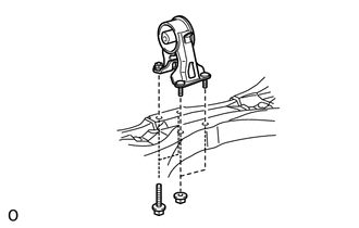
INSTALL FRONT ENGINE MOUNTING INSULATOR
Tech Tips
Perform this procedure only when replacement of the engine mounting insulator is necessary.
-
Install the engine mounting insulator with the 2 bolts.
- Torque:
- 95 N*m { 969 kgf*cm, 70 ft.*lbf }
-
-
INSTALL ENGINE HANGER
-
REMOVE ENGINE STAND
-
Attach a sling device and hang the engine with a chain block.
-
Lift the engine and remove it from the engine stand.
-
-
INSTALL ENGINE WIRE
-
Install the engine wire to the engine.
-
-
INSTALL DRIVE PLATE AND RING GEAR SUB-ASSEMBLY
-
INSTALL AUTOMATIC TRANSAXLE ASSEMBLY
-
Install the automatic transaxle assembly Click here.
-
-
INSTALL FLYWHEEL HOUSING SIDE COVER
-
INSTALL STARTER ASSEMBLY
-
TEMPORARILY INSTALL FRONT SUSPENSION CROSSMEMBER SUB-ASSEMBLY
-
Temporarily install the rear engine mounting insulator to the engine mounting bracket with the through bolt.
-
-
INSTALL ENGINE ASSEMBLY WITH TRANSAXLE
-
Place the engine on an engine lifter.
Tech Tips
Place the engine on wooden blocks or equivalent so that the engine is level.
-
Operate the engine lifter and install the engine to the vehicle.
CAUTION:
Do not raise the engine more than necessary. If the engine is raised excessively, the vehicle may also be lifted up.
Note
-
Make sure that the engine is clear of all wiring and hoses.
-
While raising the engine into the vehicle, do not allow it to contact the vehicle.
-
-
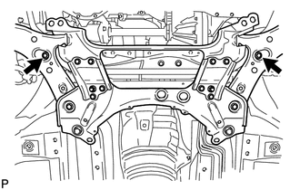
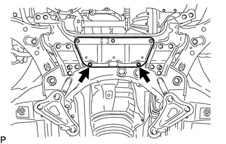
Temporarily install the front suspension crossmember with 2 new bolts.
-
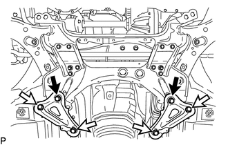
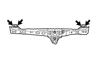
Temporarily install the member brace rear RH and LH with 2 new bolts and the 4 bolts.
Text in Illustration 
New Bolt 
Bolt -
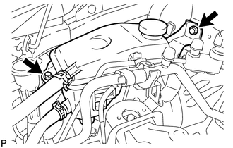
Install the engine mounting insulator LH with the through bolt and nut.
- Torque:
- 56 N*m { 571 kgf*cm, 41 ft.*lbf }
-
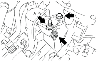
Install the engine mounting insulator RH with the bolt and 2 nuts.
- Torque:
- for bolt and nut A
- 95 N*m { 969 kgf*cm, 70 ft.*lbf }
- for nut B
- 52 N*m { 530 kgf*cm, 38 ft.*lbf }
-
Tighten the 2 front suspension member bolts.
- Torque:
- 137 N*m { 1397 kgf*cm, 101 ft.*lbf }
-
Tighten the 6 member brace rear bolts.
- Torque:
- for bolt A
- 137 N*m { 1397 kgf*cm, 101 ft.*lbf }
- for bolt B
- 93 N*m { 948 kgf*cm, 69 ft.*lbf }
-
Remove the 2 bolts and 2 engine hangers.
-
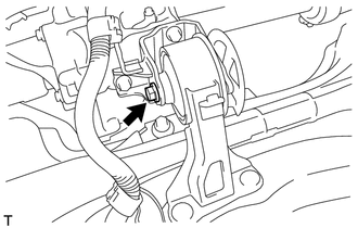
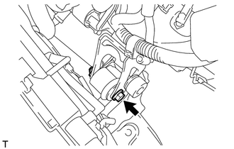
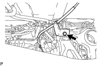
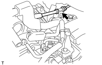
Install the air fuel ratio sensor bracket with the bolt. Then connect the air fuel ratio sensor connector.
- Torque:
- 60 N*m { 612 kgf*cm, 44 ft.*lbf }
-
-
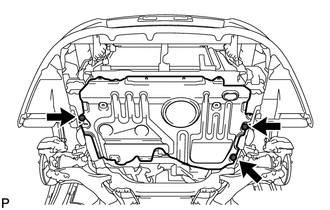
INSTALL FRONT CROSSMEMBER SUB-ASSEMBLY
-
Temporarily install the front crossmember with the 4 bolts.
-
Temporarily install the front engine mounting insulator to the front engine mounting bracket with the bolt and nut.
-
Tighten the 4 front crossmember bolts.
- Torque:
- 99 N*m { 1010 kgf*cm, 73 ft.*lbf }
-
Tighten the front engine mounting insulator bolt and nut.
- Torque:
- 145 N*m { 1479 kgf*cm, 107 ft.*lbf }
-
-
TIGHTEN FRONT SUSPENSION CROSSMEMBER SUB-ASSEMBLY
-
Tighten the rear engine mounting insulator bolt.
- Torque:
- 95 N*m { 969 kgf*cm, 70 ft.*lbf }
-
-
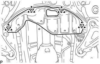
INSTALL FRONT SUSPENSION MEMBER REINFORCEMENT LH
-
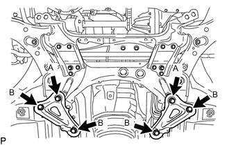
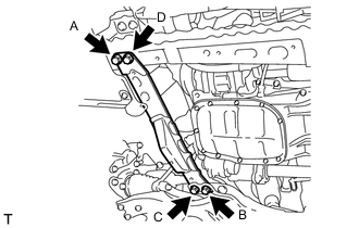
Install the reinforcement with the 4 bolts.
- Torque:
- 99 N*m { 1010 kgf*cm, 7 ft.*lbf }
Note
Tighten the bolts in the order of C, B, D and A.
-
-
INSTALL FRONT SUSPENSION MEMBER REINFORCEMENT RH
-
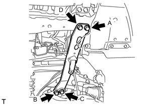
Install the reinforcement with the 4 bolts.
- Torque:
- 99 N*m { 1010 kgf*cm, 73 ft.*lbf }
Note
Tighten the bolts in the order of C, B, D and A.
-
-
INSTALL DRIVE PLATE AND TORQUE CONVERTER SETTING BOLT
-
INSTALL FRONT DRIVE SHAFT ASSEMBLY LH
-
INSTALL FRONT DRIVE SHAFT ASSEMBLY RH
-
INSTALL FRONT AXLE ASSEMBLY LH
-
Install the front axle assembly LH Click here.
-
-
INSTALL FRONT AXLE ASSEMBLY RH
Tech Tips
Use the same procedures described for the LH side.
-
CONNECT FRONT STABILIZER LINK ASSEMBLY LH
-
CONNECT FRONT STABILIZER LINK ASSEMBLY RH
Tech Tips
Use the same procedures described for the LH side.
-
INSTALL FRONT AXLE SHAFT NUT LH
-
INSTALL FRONT AXLE SHAFT NUT RH
Tech Tips
Use the same procedures described for the LH side.
-
INSTALL FRONT EXHAUST PIPE ASSEMBLY
-
INSTALL FRONT CENTER FLOOR BRACE
-
CONNECT NO. 1 STEERING COLUMN HOLE COVER SUB-ASSEMBLY
-
CONNECT NO. 2 STEERING INTERMEDIATE SHAFT ASSEMBLY
-
INSTALL COLUMN HOLE COVER SILENCER SHEET
-
CONNECT WIRE HARNESS AND HOSE
-
Connect the vacuum hose.
-
Connect the connector tube hose.
-
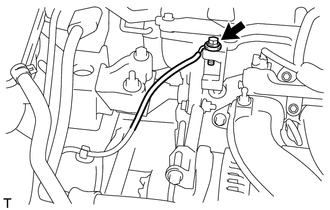
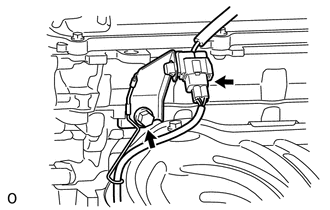
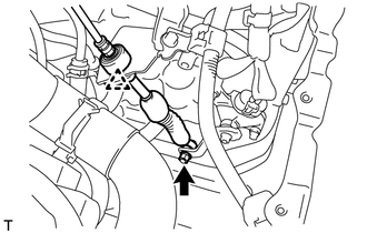
Connect the engine wire with the bolt.
- Torque:
- 29 N*m { 296 kgf*cm, 21 ft.*lbf }
-
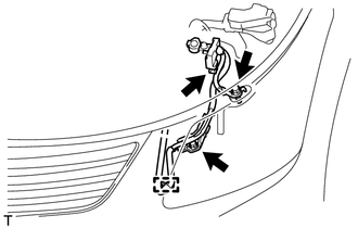
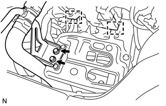
Connect the engine wire with the 2 bolts and clamp.
- Torque:
- 8.4 N*m { 86 kgf*cm, 74 in.*lbf }
-
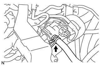
Connect the connector to the battery current sensor.
-
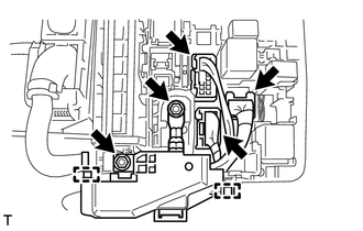
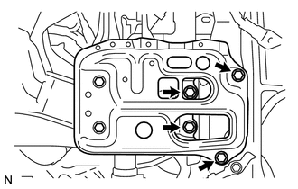
Attach the 2 clamps to install the wire harness, and then install the 2 nuts.
- Torque:
- 8.4 N*m { 86 kgf*cm, 74 in.*lbf }
-
Connect the 3 wire harness connectors to the engine room No. 1 junction block.
-
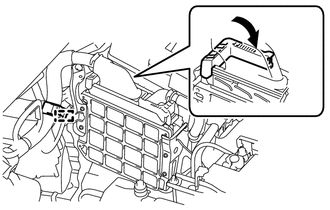
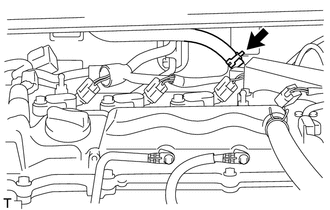
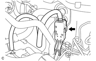
Connect the ECM connector and lower the lever.
Note
-
When connecting the connector, make sure that dirt, water or other foreign matter does not get caught between the connector and other parts.
-
Make sure that the lever is securely lowered.
-
-
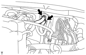
Connect the wire harness clamp.
-
Connect the 2 oil cooler hoses to the oil cooler tube.
-
-
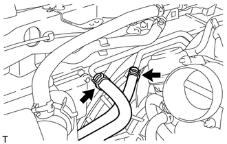
CONNECT HEATER WATER HOSE
-
Connect the 2 heater water hoses.
-
-
CONNECT FUEL TUBE SUB-ASSEMBLY
-
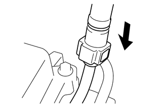
Connect the fuel tube connector and fuel pipe.
Note
Align the fuel tube connector with the pipe, and then push the fuel tube connector on until the retainer makes a "click" sound. If the connection is tight, apply a small amount of engine oil to the tip of the pipe. After connecting the connector, pull the pipe and connector to make sure that they are securely connected. A206121
-
Attach the claw to install the No. 1 fuel pipe clamp.
-
-
CONNECT NO. 1 RADIATOR HOSE
-
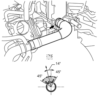
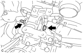
*1 Top Connect the radiator hose to the cylinder head.
Tech Tips
The direction of the hose clamp is indicated in the illustration.
-
-
CONNECT TRANSMISSION CONTROL CABLE ASSEMBLY
-
Connect the transmission control cable support together with the cable with the nut.
- Torque:
- 5.0 N*m { 51 kgf*cm, 44 in.*lbf }
-
Connect the transmission control cable to the control cable bracket.
-
Connect the transmission control cable to the bracket with a new clip.
-
Connect the transmission control cable to the control shaft lever with the nut.
- Torque:
- 12 N*m { 122 kgf*cm, 9 ft.*lbf }
-
-
INSTALL BATTERY CARRIER
-
Install the battery carrier with the 4 bolts.
- Torque:
- 19 N*m { 189 kgf*cm, 14 ft.*lbf }
-
Install the radiator pipe with the 2 bolts.
- Torque:
- 19 N*m { 189 kgf*cm, 14 ft.*lbf }
-
Connect the 2 wire harness clamps.
-
-
INSTALL BATTERY TRAY
-
INSTALL BATTERY
-
INSTALL BATTERY CLAMP SUB-ASSEMBLY
-
Install the battery clamp with the bolt and nut.
- Torque:
- for bolt
- 17 N*m { 168 kgf*cm, 12 ft.*lbf }
- for nut
- 3.5 N*m { 36 kgf*cm, 31 in.*lbf }
-
Connect the cable to the positive (+) battery terminal.
- Torque:
- 5.4 N*m { 55 kgf*cm, 48 in.*lbf }
-
-
INSTALL AIR CLEANER CASE SUB-ASSEMBLY
-
INSTALL AIR CLEANER CAP SUB-ASSEMBLY
-
CONNECT COMPRESSOR WITH PULLEY ASSEMBLY
-
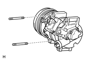
Using an E8 "TORX" socket wrench, connect the compressor with pulley assembly with the 2 stud bolts.
- Torque:
- 9.8 N*m { 100 kgf*cm, 87 in.*lbf }
-
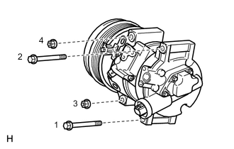
Install the 2 bolts and 2 nuts.
- Torque:
- 25 N*m { 255 kgf*cm, 18 ft.*lbf }
Tech Tips
Tighten the bolts and the nuts in the order shown in the illustration.
-
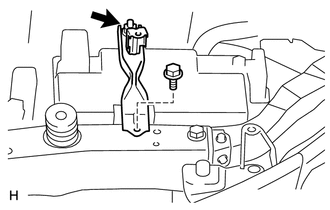
Connect the connector.
-
-
CONNECT NO. 2 RADIATOR HOSE
-
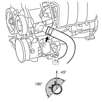
*1 Top Connect the radiator hose to the water inlet.
Tech Tips
The direction of the hose clamp is indicated in the illustration.
-
-
INSTALL GENERATOR ASSEMBLY
-
INSTALL V-RIBBED BELT
-
ADJUST V-RIBBED BELT
-
CONNECT RADIATOR RESERVOIR ASSEMBLY
-
Install the grommet to the radiator reservoir.
-
Connect the radiator reservoir with the 2 bolts.
- Torque:
- 5.0 N*m { 51 kgf*cm, 44 in.*lbf }
-
-
CONNECT CABLE TO NEGATIVE BATTERY TERMINAL
Note
When disconnecting the cable, some systems need to be initialized after the cable is reconnected Click here.
-
ADD AUTOMATIC TRANSAXLE FLUID
-
INSPECT AUTOMATIC TRANSAXLE FLUID LEVEL
-
Inspect automatic transaxle fluid level Click here.
-
-
ADD ENGINE COOLANT
-
ADD ENGINE OIL
-
INSPECT FOR FUEL LEAK
-
INSPECT FOR COOLANT LEAK
-
INSPECT FOR OIL LEAK
-
INSPECT FOR EXHAUST GAS LEAK
-
INSPECT V-RIBBED BELT
-
INSPECT IGNITION TIMING
-
INSPECT ENGINE IDLE SPEED
-
INSPECT CO/HC
-
ADJUST FRONT WHEEL ALIGNMENT
-
Adjust the front wheel alignment Click here.
-
-
INSTALL NO. 2 ENGINE UNDER COVER
-
Install the under cover with the 4 clips.
-
-
INSTALL CENTER NO. 4 ENGINE UNDER COVER
-
Install the under cover with the 2 clips.
-
-
INSTALL REAR ENGINE UNDER COVER RH
-
INSTALL REAR ENGINE UNDER COVER LH
-
Install the under cover LH with the 5 clips.
-
-
INSTALL NO. 1 ENGINE UNDER COVER (for Rough Road Area Specification Vehicles)
-
Install the under cover with the 3 clips.
-
-
INSTALL NO. 1 ENGINE UNDER COVER
-
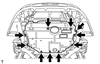
Install the under cover with the 10 clips.
-
-
INSTALL FRONT LOWER BUMPER ABSORBER
-
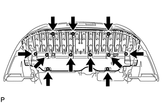
Install the front lower bumper absorber with the 3 screws and 8 bolts.
-
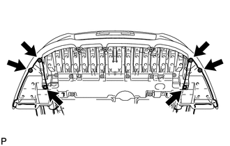
Install the 4 screws and 2 bolts.
-
-
INSTALL RADIATOR SUPPORT OPENING COVER
-
INSTALL NO. 2 CYLINDER HEAD COVER