REPAIR INSTRUCTION PRECAUTION
-
BASIC REPAIR HINT
-
HINTS ON OPERATIONS
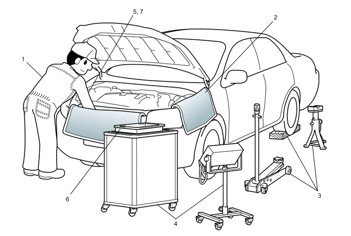
1 Attire
-
Always wear a clean uniform.
-
A hat and safety shoes must be worn.
2 Vehicle protection Prepare a grille cover, fender cover, seat cover and floor mat before starting work. 3 Safety procedures
-
When working with 2 or more persons, be sure to check the safety of one another.
-
If working on high temperature, high pressure, rotating, moving or vibrating parts, wear appropriate safety equipment and take extra care not to injure yourself or others.
-
When jacking up the vehicle, be sure to support the vehicle at the specified locations with safety stands.
-
When lifting up the vehicle, use appropriate safety equipment.
4 Preparation of tools and measuring equipment Before starting work, prepare a tool stand, SST, measuring equipment, oil, and any replacement parts required. 5 Removal and installation, disassembly and assembly operations
-
Diagnose with a thorough understanding of proper procedures and of the reported problem.
-
Before removing any parts, check the general condition of the assembly and for deformation and damage.
-
If the procedure is complicated, take notes. For example, note the total number of electrical connections, bolts or hoses removed. Add matchmarks to ensure reassembly of components in the original positions. Temporarily mark hoses and their fittings if needed.
-
Clean and wash the removed parts if necessary and assemble them after a thorough check.
6 Removed parts
-
Place the removed parts in a separate box to avoid mixing them up with new parts or contaminating the new parts.
-
For non-reusable parts such as gaskets, O-rings and self-locking nuts, replace them with new ones as instructed in this manual.
-
Retain the removed parts for customer inspection, if requested.
7* Checks to perform after work is finished
-
Make sure that removed and installed parts (oil filler cap, level dipstick, floor mat, etc.) are properly installed/tightened.
-
Make sure that none of the cloths or tools that were used have been left in the motor compartment or within the vehicle.
-
Check that there are no oil leaks.
CAUTION:
*: Be sure to perform these checks properly. Not performing these checks properly after finishing work can lead to a serious accident or injury.
-
-
JACKING UP AND SUPPORTING THE VEHICLE
-
Care must be taken when jacking up and supporting the vehicle. Be sure to lift and support the vehicle at the proper locations.
-
-
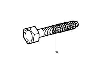
*a Seal Lock Adhesive PRECOATED PARTS
-
Precoated parts are bolts and nuts that are coated with seal lock adhesive at the factory.
-
If a precoated part is retightened, loosened or moved in any way, it must be recoated with the specified adhesive.
-
When reusing a precoated part, clean off the old adhesive and dry the part with compressed air. Then apply new seal lock adhesive appropriately to that part.
-
Some seal lock agents harden slowly. You may have to wait for the seal lock adhesive to harden.
-
-
GASKETS
-
When necessary, use a sealer on gaskets to prevent leaks.
-
-
BOLTS, NUTS AND SCREWS
-
Carefully follow all the specifications for tightening torque. Always use a torque wrench.
-
Make sure that no foreign matter (burrs, paint, etc.) gets trapped under the heads of the bolts and nuts when tightening them.
-
-
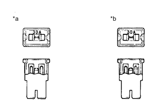
*a INCORRECT *b CORRECT FUSES
-
When inspecting a fuse, check that the wire of the fuse is not broken.
-
If the wire of a fuse is broken, confirm that there are no shorts in its circuit.
-
When a fuse is replaced, a fuse with the same amperage rating must be used.
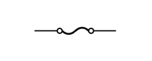
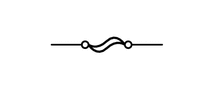
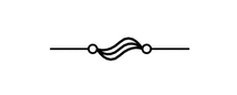
Illustration Symbol Part Name Abbreviation 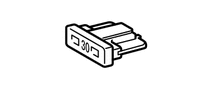
FUSE FUSE 
MEDIUM CURRENT FUSE M-FUSE 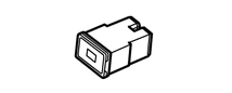
HIGH CURRENT FUSE H-FUSE 
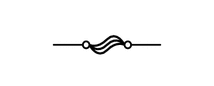
FUSIBLE LINK FL 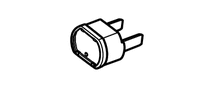
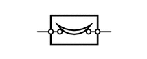
CIRCUIT BREAKER CB 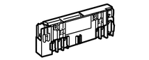
FUSIBLE LINK FL
-
-
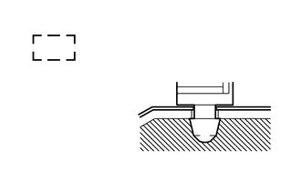
CLIPS
-
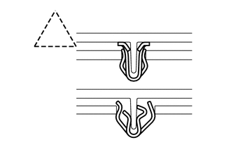
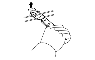
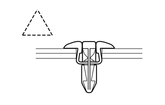
The removal and installation methods of typical clips used for vehicle body parts are shown in the table below.
Tech Tips
If clips are damaged during a procedure, always replace the damaged clips with new ones.
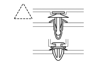
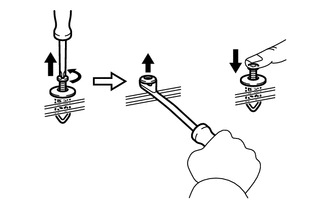
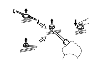
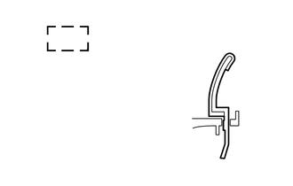
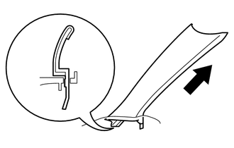
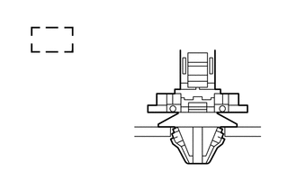
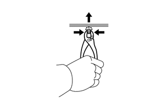
Shape (Example) Removal/Installation 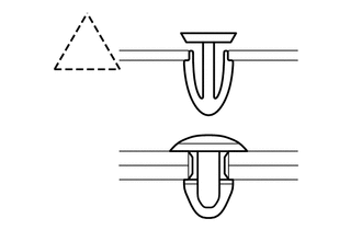
Remove the clips with a clip remover or pliers.
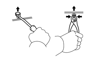
Remove the clips using a clip remover or a screwdriver with its tip wrapped with protective tape.
Remove the clips with a wide scraper to prevent panel damage.
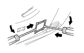
Remove the clips by pushing the center pin through and pulling out the shell.
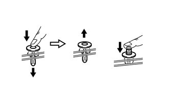
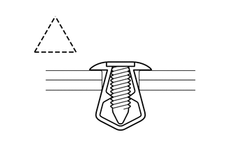
Remove the clips by unscrewing the center pin and prying out the shell.
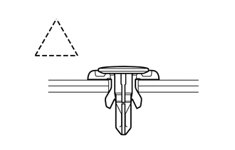
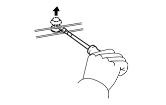
Remove the clips by prying out the pin using a screwdriver with its tip wrapped with protective tape and then prying out the shell.
-
-
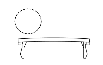
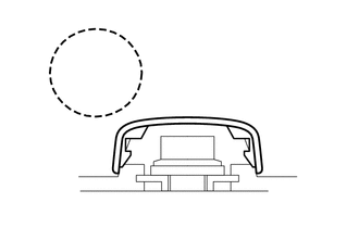
CLAWS
-
The removal and installation methods of typical claws used for vehicle body parts are shown in the table below.
Tech Tips
If claws are damaged during a procedure, always replace the cap or cover that has damaged claws with a new one.
Shape (Example) Illustration / Procedures 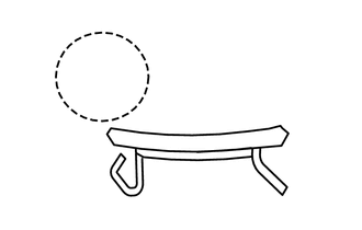
Disengage the claws using a screwdriver with its tip wrapped with protective tape to remove the caps or covers.
Disengage the claws using a screwdriver with its tip wrapped with protective tape to remove the caps or covers.
Disengage the claws using a screwdriver with its tip wrapped with protective tape to remove the caps or covers.
-
-
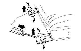
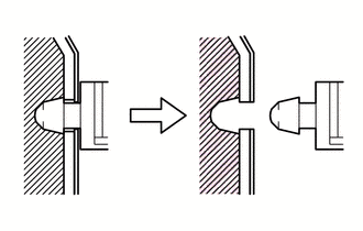
HINGES, GUIDES, CLAMPS, PINS, ETC.
-
The removal and installation methods of typical hinges, guides, clamps and pins used for vehicle body parts are shown in the table below.
Tech Tips
If clamps are damaged during a procedure, always replace the cap or cover that has damaged clamps with a new one.
Shape (Example) Removal/Installation 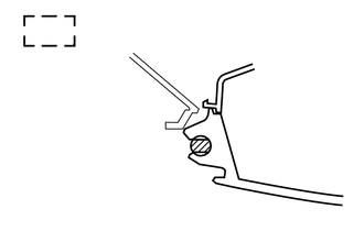
Pull away from the pins to disengage.
Disengage the pins by pulling.
Remove the clamps with pliers.
Disengage the pins by pulling.
-
-
REMOVAL AND INSTALLATION OF VACUUM HOSES
-
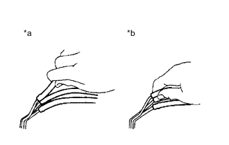
*a INCORRECT *b CORRECT To disconnect a vacuum hose, pull and twist on the end. Do not pull on the middle of the hose as this may damage the hose.
-
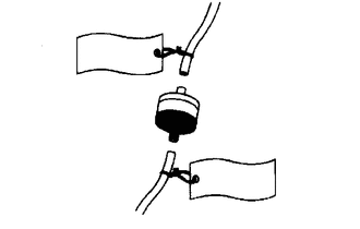
When disconnecting vacuum hoses, use tags to identify where they should be reconnected.
-
After completing any hose related repairs, double-check that the vacuum hoses are properly connected. The label under the hood shows the proper layout.
-
When using a vacuum gauge, never force the hose onto a connector that is too large. If a hose has been stretched, air may leak. Use a step-down adapter if necessary.
-
-
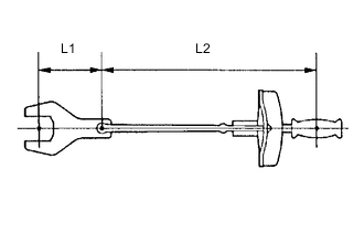
TORQUE WHEN USING TORQUE WRENCH WITH EXTENSION TOOL
-
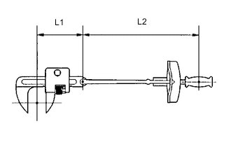
Use the formula below to calculate special torque values for situations where SST or an extension tool is combined with a torque wrench.
T' Reading of torque wrench (N*m (kgf*cm, ft.*lbf)) T Torque (N*m (kgf*cm, ft.*lbf)) L1 Length of SST or extension tool (cm (in.)) L2 Length of torque wrench (cm (in.)) Note
If an extension tool or SST is combined with a torque wrench and used to tighten to a torque specification in this manual, the actual torque will be excessive and parts will be damaged.
-
-
-
PRECAUTIONS FOR HIGH-VOLTAGE CIRCUIT INSPECTION AND SERVICE
CAUTION:
This vehicle has a hybrid system that operates at voltages up to 650 V. The hybrid system uses an EV battery that contains an electrolyte which is a strong alkali solution that includes potassium hydroxide. Be sure to follow the instructions in this manual to handle the system correctly. Failure to do so may result in serious injury or electrocution.
-
Technicians must undergo special training to be able to service and inspect the high-voltage system.
-
All high-voltage wire harnesses and connectors are colored orange. The EV battery and other high-voltage components have "High Voltage" caution labels. Do not carelessly touch these wires or components.
-
When there is a problem with the wire harness or connector of a high-voltage circuit, repairs to the harness or connector should not be attempted. Replace damaged or malfunctioning high voltage cables or connectors.
-
Before performing any of the following operations, be sure to follow all safety measures, such as turning the power switch off, wearing insulated gloves, and removing the service plug grips from both the FC stack and EV battery to prevent electrocution.
-
Working on the high-voltage system
-
Disconnecting the low voltage connector of the inverter with converter assembly
-
Disconnecting the low voltage connector of the EV battery
-
Disconnecting the low voltage connector of the FC stack assembly
-
Disconnecting the low voltage connector of the FC converter assembly
-
-
After removing the service plug grips from the FC stack and EV battery, store them according to the following guidelines to prevent other technicians from accidentally reconncting them while you are working on the high-voltage systems.
-
Carry the service plug grip removed from the EV battery in your pocket to prevent other technicians from accidentally reconnecting it while you are servicing the vehicle.
-
Store the service plug grip removed from the FC stack in a safe location and use the "CATION: HIGH VOLTAGE DO NOT TOUCH" sign to notify other technicians that you are working on the hign-voltage system.
Note
-
After turning the power switch off, waiting time may be required before disconnecting the cable from the negative (-) auxiliary battery terminal. Therefore, make sure to read the disconnecting the cable from the negative (-) auxiliary battery terminal notices before proceeding with work.
-
After removing the service plug grip, turning the power switch on (READY) may cause a malfunction. Do not turn the power switch on (READY) unless instructed by the repair manual.
Tech Tips
Remove the service plug grips from both the FC stack and EV battery, in no particular order.
-
-
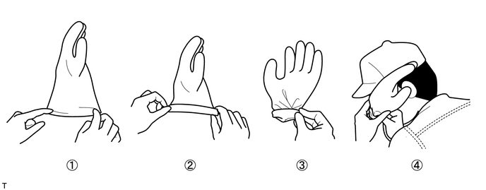
Before using insulated gloves, be sure to check them for cracks, tears and other types of damage by performing the following procedure.
-
Place the glove on its side.
-
Roll the opening up 2 or 3 times.
-
Fold the opening in half to close it.
-
Confirm that there are no air leaks.
-
-
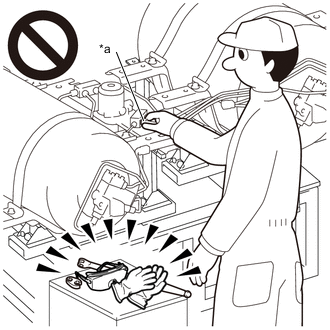
When servicing the vehicle, do not carry metal objects like mechanical pencils or rulers that can be dropped accidentally and cause a short circuit.
-
Before touching a bare high-voltage terminal, wear insulated gloves and use a tester to make sure that the terminal voltage is 0 V.
-
After disconnecting or exposing a high-voltage connector or terminal, insulate it immediately using insulating tape.
-
Bolts and nuts for high-voltage terminals should be tightened firmly to the specified torque. Both insufficient and excessive torque can cause failure.
-
Use the "CAUTION: HIGH VOLTAGE DO NOT TOUCH" sign to notify other technicians that the high-voltage system is being inspected and/or repaired.
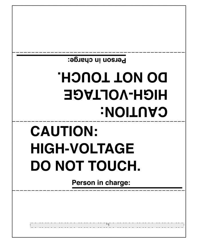
*1 When performing work on the EV system, fold this sign and put it on the roof of the vehicle. -
Use the "CAUTION: HIGH PRESSURE GAS DO NOT TOUCH" sign to notify other technicians that the high-pressure gas system is being inspected and/or repaired.
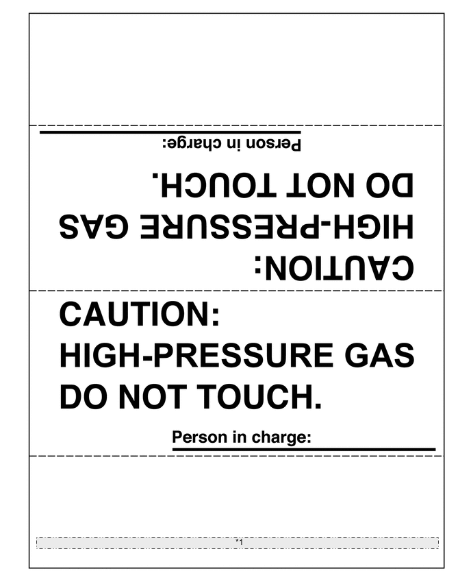
*1 Place signs [HIGH PRESSURE GAS WORK IN PROGRESS - DO NOT TOUCH!], etc. to warn other technicians to be cautious. (An example sign is included, so make a copy and use it.) -
After servicing the high-voltage system and before reinstalling the service plug grip, check again that you have not left a part or tool inside, that the high-voltage terminals are firmly tightened, and that the connectors are correctly connected.
-
When performing work involving high-voltage wires, use either a tool wrapped with vinyl insulation tape or an insulated tool.
-
When installing hybrid system components such as the EV battery, make sure that the polarity of all connections is correct.
-
-
ACTIONS TO BE TAKEN WHEN A WARNING LIGHT IS ILLUMINATED
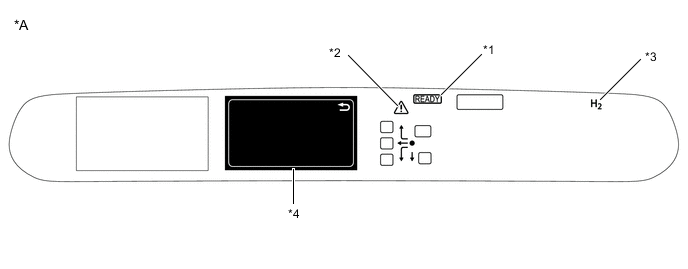
*A for LHD - - *1 READY Indicatot *2 Master Warning Light *3 Hydrogen Leak Warning Light *4 Multi-information Display 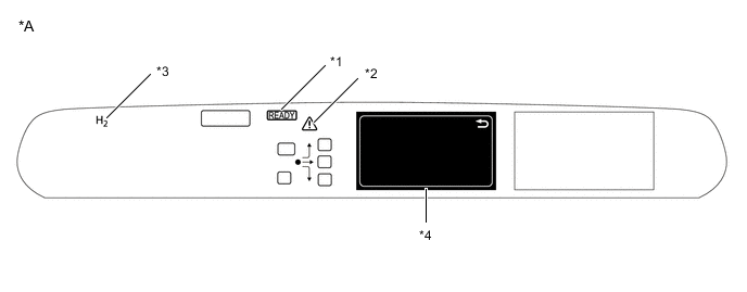
*A for RHD - - *1 READY Indicatot *2 Master Warning Light *3 Hydrogen Leak Warning Light *4 Multi-information Display
-
If one of the warning lights (2) to (4) illuminates, connect the GTS to the DLC3 to check the DTCs (Diagnostic Trouble Codes). Then, refer to the applicable troubleshooting steps in this manual to inspect and repair the affected area. The foregoing actions are also required if the READY indicator does not illuminate when attempting to turn the power switch on (READY).
Indicator Light Vehicle Condition (1) READY Indicatot (To Drive) Illuminates when the power switch is turned on (READY), indicating that the vehicle is ready to be driven. (2) Master Warning Light Depending on the warning, the master warning light comes on or flashes to indicate that a warning is currently being displayed on the multi-information display. Depending on the warning, the buzzer may also sound. (3) Charge Warning Illuminates when there is a malfunction in the charging system.
(Be sure to check the DTCs (Diagnostic Trouble Codes) if this light illuminates together with the master warning light.)
(4) Hydrogen Warning Light Illuminates if the hydrogen concentration is at or above the threshold value. (Approximately 2%)
-
-
ACTIONS TO BE TAKEN WHEN BATTERIES ARE DISCHARGED
Tech Tips
The vehicle uses a 12 V auxiliary and a 244.8 V EV battery. Therefore, there are 2 recharging methods when the batteries are discharged.
-
Perform this procedure when the auxiliary battery is fully discharged.
Tech Tips
The following problems indicate that the auxiliary battery is discharged:
-
No display appears on the instrument panel when the power switch is turned on (IG).
-
The FC control system does not start.
-
The headlights are dim.
-
The sound from the horn is weak.
Note
-
Never use a quick charger.
-
The booster terminal cannot be used to rescue a vehicle with a discharged battery.
-
Engage the parking brake.
-
Turn the power switch off and remove the key from the interior detection area.
-
Remove the No. 1 relay block cover.
-
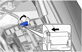
Disengage the claw and open the cover of the booster terminal.
-
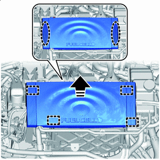

Place Hands Here 
Remove in this Direction Disengage the grommets and remove the inverter cover.
-
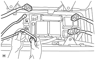
Using booster cables, connect the 12 V auxiliary battery of the rescue vehicle and the auxiliary battery of the stalled vehicle as shown in the illustration.
Tech Tips
Use the booster terminal in the motor compartment.
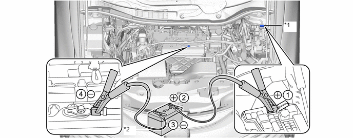
*1 Booster Terminal *2 Auxiliary Battery of Rescue Vehicle Connecting Sequence Connecting Location 1 Positive booster terminal of stalled vehicle 2 Positive auxiliary battery terminal of rescue vehicle 3 Negative auxiliary battery terminal of rescue vehicle 4 Position shown in the illustration on stalled vehicle -
Start the engine of the rescue vehicle and run the engine at a speed slightly higher than usual.
-
Turn the power switch on (READY).
Note
Immediately disconnect the booster cables in the reverse order of connection after the hybrid system has started. Do not leave the booster cables connected because they are not designed for recharging purposes.
If the hybrid system fails to start and the EV battery warning message is displayed on the multi-information display, the EV battery may be discharged.
-
-
When the EV battery is discharged:
-
Replace the EV battery.
Tech Tips
Perform this operation when the EV battery is discharged or low, or if a low traction battery warning message is displayed on the multi-information display and DTC P0AF8-816, P3000-388 or 389 is stored in the EV control ECU.
-
-
-
ACTIONS TO BE TAKEN FOR VEHICLES DAMAGED BY IMPACT (Hydrogen System)
CAUTION:
-
Hydrogen gas is a colorless, odorless and flammable gas.
-
Because the flammable concentration range is wide (4 - 74.5%) and the energy required for ignition is extremely low, even static electricity can easily cause hydrogen gas to ignite. While working on the vehicle, if the sound of hydrogen gas leaking (a loud hissing sound) can be heard, measure the hydrogen gas concentration with a hydrogen concentration detector. If the hydrogen gas concentration near the vehicle is more than 4%, there is a danger that the hydrogen could ignite, so move away from the vehicle immediately.
-
Even after the vehicle is stopped, there is still hydrogen gas remaining in hydrogen equipment such as the hydrogen tanks and in the hydrogen piping. To avoid fires or explosions, do not cut or destroy hydrogen equipment or hydrogen piping.
-
Because of the danger of hydrogen igniting, when a hydrogen leak is present, do not use electrical devices or rescue devices that could generate static electricity.
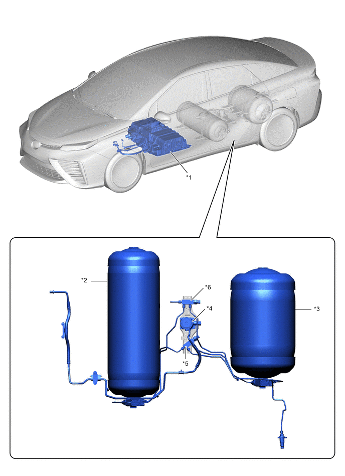
*1 FC Stack Assembly *2 No. 1 Hydrogen Tank Assembly *3 No. 2 Hydrogen Tank Assembly *4 Hydrogen Supply Regulator Assembly *5 Hydrogen Tube Joint (Inlet Side) *6 Hydrogen Tube Joint (Outlet Side)
-
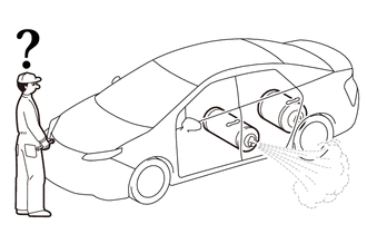
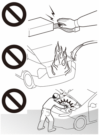
In case of a vehicle fire
-
A fuel cell vehicle (FCV) contains compressed hydrogen gas.
-
When spraying water on the fire, prepare for the hydrogen to ignite, and keep your distance from the vehicle while spraying water.
-
In particular, spray a large amount of water on the hydrogen tanks under the floor at the rear of the vehicle to keep them cool.
-
If the hydrogen has ignited, completely extinguishing the fire could cause unburned hydrogen gas to collect, which could result in a secondary explosion. To prevent this, spray water to keep the fire from spreading to the surroundings, and wait for the fire to burn itself out (when all the fuel has been expended).
-
To prevent the hydrogen tanks from exploding due to abnormal temperature / pressure increase, pressure relief device designed into the hydrogen tanks will open when the temperature exceeds 110°C, causing the hydrogen gas inside the tanks to be discharged toward the rear of the vehicle.
-
Although pure hydrogen gas burns with a nearly colorless flame that is very difficult to see, in the case of a vehicle fire, the flames will be mixed with other flames from nearby combustible materials, making them easier to see.
-
A peculiar characteristic of hydrogen flame is that while the temperature of the flame itself is extremely high, because the flame emits very little radiant heat, it is difficult to feel the heat of the fire when approaching it.
-
-
Make sure that the sound of hydrogen gas leaking (a loud hissing sound) cannot be heard.
-
When approaching the vehicle, approach from the front side of the vehicle.
-
When a leaking sound can be heard, there is a danger of igniting the hydrogen, so move away from the vehicle immediately.
-
Check that the leaking sound has stopped before moving on to the following procedure.
-
-
Using a hydrogen concentration detector, measure the hydrogen concentration around the vehicle to make sure that it does not exceed 4%.
-
If the concentration exceeds 4%, there is a danger of igniting the hydrogen, so move away from the vehicle immediately.
-
If a fan or blower is available, blow air to reduce the hydrogen concentration. When approaching the vehicle, approach from the upwind side.
-
Periodically measure the hydrogen concentration, and make sure that the hydrogen concentration does not exceed 4% before moving on to the following procedure.
-
-
-
ACTIONS TO BE TAKEN FOR VEHICLES DAMAGED BY IMPACT (High-voltage System)
CAUTION:
This vehicle has a hybrid system that operates at voltages up to 650 V. The hybrid system uses an EV battery that contains an electrolyte which is a strong alkali solution that includes potassium hydroxide. Be sure to follow the instructions in this manual to handle the system correctly. Failure to do so may result in serious injury or electrocution.
-
Items to be prepared for the accident site
-
Protective clothing (insulated gloves, rubber gloves, goggles and safety shoes)
-
20 liters (21.1 US qts, 17.6 Imp. qts) saturated boric acid solution (obtain 800 g (1.76 lb) of boric acid powder, put it into a container, and dissolve it in water)
-
Red litmus paper
-
ABC fire extinguisher (effective against both oil flames and electrical flames)
-
A shop rag or piece of cloth (for wiping up the neutralized electrolyte)
-
Insulating tape (for insulating cables)
-
Electrical tester
-
-
Actions to be taken at the accident site
CAUTION:
-
Do not touch any bare cables that may have high-voltage. If a cable must be touched or if accidental contact is possible, wear insulated gloves and insulate the cable using insulating tape.
-
If the vehicle catches on fire, use an ABC fire extinguisher to extinguish the fire. Trying to extinguish a fire using only a small amount of water can be more dangerous than effective. Use a substantial amount of water or wait for firefighters.
-
Visually check the EV battery and the immediate area for any electrolyte leakage. Do not touch any leaked liquid because it could be a highly alkaline electrolyte.
-
If the vehicle is submerged in water, work on the vehicle only after the vehicle has been pulled out of the water.
-
Check the vicinity of the EV battery for any leakage of the electrolyte.
CAUTION:
-
Do not touch any leaked liquid because it could be a highly alkaline electrolyte. Wear rubber gloves and goggles, neutralize the liquid with a saturated boric acid solution and then apply red litmus paper to the liquid. Check that the paper does not turn blue. Wipe up the neutralized liquid with a shop rag or piece of cloth.
-
If the electrolyte comes in contact with your skin, use a saturated boric acid solution or a large amount of water to wash it off. If the electrolyte comes in contact with an article of clothing, take it off immediately.
-
If the electrolyte comes in contact with your eyes, call out loudly for help. Do not rub your eyes. Wash them immediately with a large amount of water and seek medical care.
-
-
If damage to any of the high-voltage components and cables is suspected, cut the high-voltage circuit using the following procedure.
CAUTION:
Be sure to wear insulated gloves, goggles and safety shoes.
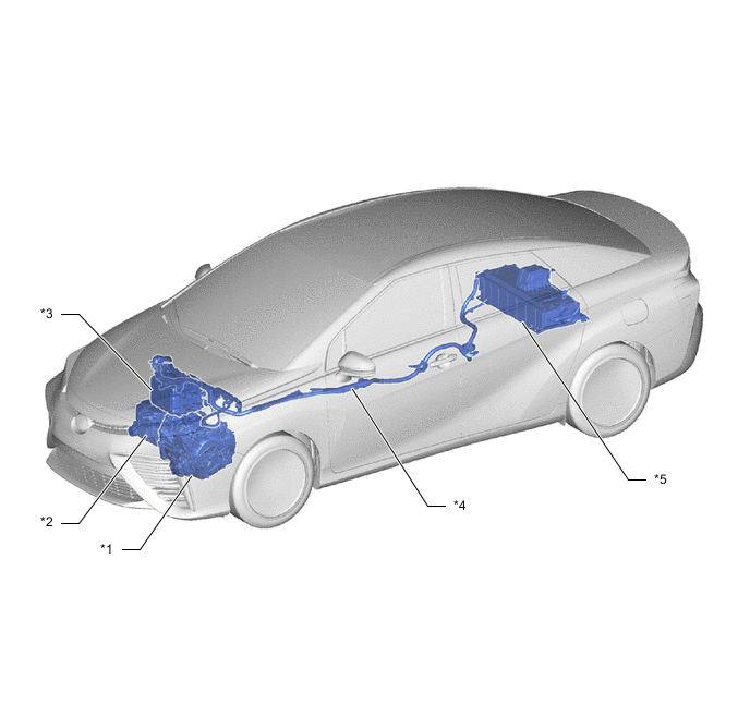
*1 FCV TRANSAXLE WITH MOTOR ASSEMBLY *2 FC AIR COMPRESSOR WITH MOTOR ASSEMBLY *3 INVERTER WITH CONVERTER ASSEMBLY *4 FRAME WIRE *5 EV BATTERY - - 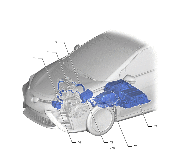
*1 FC STACK ASSEMBLY *2 FC CONVERTER ASSEMBLY *3 MOTOR COMPARTMENT RELAY BLOCK *4 COMPRESSOR WITH MOTOR ASSEMBLY *5 NO. 3 MOTOR WIRE *6 MG-IGCT FUSE *7 FC CONVERTER POWER OUTLET CABLE *8 HYDROGEN PUMP INVERTER CABLE -

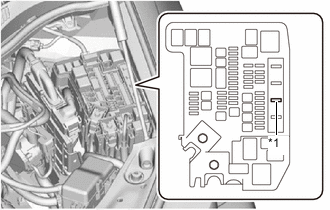
*1 IG2-MAIN Fuse Turn the power switch off.
Tech Tips
If the power switch cannot be turned off, remove the IG2-MAIN fuse from the motor compartment relay block. Confirm that the READY light is off.
-
Disconnect the cable from the negative (-) auxiliary battery terminal.
-
While wearing insulated gloves, remove the service plug grips.
for FC:
for EV:
Note
After removing the service plug grips, do not turn the power switch on (READY), unless instructed by the repair manual because this may cause a malfunction.
-
-
Moving the damaged vehicle
If any of the following conditions are met, tow the vehicle away using a tow truck.
-
One or more of the high-voltage components and cables are damaged.
-
One or more of the hydrogen system components and pipes are damaged.
-
Components related to driving, the transaxle, or the fuel system are damaged.
-
The master warning light is on.
-
The READY light does not come on when attempting to turn the power switch on (READY).
CAUTION:
Before towing the vehicle away using a tow truck, disconnect the cable from the negative (-) auxiliary battery terminal and remove the service plug grips.
for FC:
for EV:
Note
Perform the procedure below if the master warning light turns on, or there are abnormal noises, unusual smells, or strong vibrations while driving:
-
Park the vehicle in a safe place.
-
Apply the parking brake, and then push the P position switch.
-
Turn the power switch off, and disconnect the cable from the negative (-) auxiliary battery terminal.
-
Remove the service plug grips while wearing insulated gloves.
-
-
Actions required after moving the damaged vehicle
-
Procedure
If you see any liquid on the road surface, it could be highly alkaline electrolyte.
Wear rubber gloves and goggles, neutralize the liquid with a saturated boric acid solution, and then apply red litmus paper to the liquid. Check that the paper does not turn blue. Wipe up the neutralized liquid with a shop rag or piece of cloth.
-
-
Items to be prepared (when repairing a damaged vehicle)
-
Protective clothing (insulated gloves, rubber gloves, goggles and safety shoes)
-
20 liters (21.1 US qts, 17.6 Imp. qts) saturated boric acid solution (obtain 800 g (1.76 lb) of boric acid powder, put it into a container, and dissolve it in water)
-
Red litmus paper
-
A shop rag or piece of cloth (for wiping off the electrolyte)
-
Insulating tape (for insulating cables)
-
Electrical tester
-
-
Precautions to be observed when servicing a damaged vehicle
CAUTION:
Always follow instructions to ensure safety.
-
Wear insulated or rubber gloves, goggles, and safety shoes.
-
Check the EV battery and immediate area for any electrolyte leakage.
CAUTION:
-
Do not touch any leaked liquid because it could be a highly alkaline electrolyte. Wear rubber gloves and goggles, neutralize the liquid with saturated boric acid solution and then apply red litmus paper to the liquid. Check that the paper does not turn blue. Wipe up the neutralized liquid with a shop rag or piece of cloth.
-
If the electrolyte comes in contact with your skin, use a saturated boric acid solution or a large amount of water to wash it off. If the electrolyte comes in contact with an article of clothing, take it off immediately.
-
If the electrolyte comes in contact with your eyes, call out loudly for help. Do not rub your eyes. Wash them immediately with a large amount of water and seek medical care.
-
-
Do not touch any bare cables that could be high voltage cables. If a cable must be touched or if accidental contact is possible, follow the following instructions: 1) wear insulated gloves and goggles, 2) measure the voltage between the cable and body ground using an electrical tester, and 3) insulate the cable using insulating tape.
-
If damage to any of the high-voltage components and cables is suspected, cut the high-voltage circuit using the procedure below.
CAUTION:
Do not touch any bare cables that may have high-voltage. If a cable must be touched or if accidental contact is possible, wear insulated gloves and insulate the cable using insulating tape.
-
*1 IG2-MAIN Fuse Turn the power switch off.
Tech Tips
If the power switch cannot be turned off, remove the IG2-MAIN fuse from the motor compartment relay block. Confirm that the READY light is off.
-
Disconnect the cable from the negative (-) auxiliary battery terminal.
-
While wearing insulated gloves, remove the service plug grips.
Note
After removing the service plug grip, do not turn the power switch on (READY), unless instructed by the repair manual because this may cause a malfunction.
-
-
Precautions to be taken when disposing of an EV battery
-
When disposing of an EV battery, make sure to return it through an authorized collection agent who is capable of handling it safely. If the EV battery is returned via the manufacturer specified route, it will be returned properly and in a safe manner by an authorized collection agent.
CAUTION:
-
Accidents such as electric shock may result if the EV battery is disposed of improperly or abandoned. Therefore, make sure to return all EV batteries through an authorized collection agent.
-
After removing the EV battery, keep it away from water. Exposure to water may cause the EV battery to produce heat, resulting in a fire.
-
-
-
Precautions to be observed when towing
-
Tow the damaged vehicle with its front and rear wheels lifted off the ground.
CAUTION:
Towing the damaged vehicle with its wheels on the ground will cause the motor to generate electricity. This electricity could, depending on the nature of the damage, leak and cause a fire.
-
-
Towing with the 4 wheels on the ground
CAUTION:
-
If the vehicle needs to be towed using a cable or chain with all 4 wheels on the ground, do not exceed 5 km/h (3 mph) and tow only for a short distance and then have the vehicle towed by a truck.
-
Turn the power switch on (IG), move the shift lever to N and confirm that neutral (N) has been selected.
-
Make sure not to turn the power switch off while the vehicle is being towed. Park (P) may be selected, resulting in damage or an accident.
-
If any abnormality is present in the damaged vehicle during towing, stop towing immediately.
Tech Tips
-
Neutral (N) cannot be selected if the auxiliary battery is disconnected.
-
There is a possibility that neutral (N) cannot be selected when parts related to the transmission control ECU have a malfunction.
-
-
-
FOR VEHICLES EQUIPPED WITH SRS AIRBAG AND SEAT BELT PRETENSIONER
This vehicle is equipped with a Supplemental Restraint System (SRS).
CAUTION:
-
Before performing pre-disposal deployment of any SRS component, review and closely follow all applicable environmental and hazardous material regulations. Pre-disposal deployment may be considered hazardous material treatment.
-
Failure to carry out the service operations in the correct sequence could cause the SRS to unexpectedly deploy during servicing and lead to a serious injury. Furthermore, if a mistake is made when servicing the SRS, it is possible that the SRS may fail to operate properly. Before servicing (including removal or installation of parts, inspection or replacement), be sure to read the following section carefully.
-
GENERAL NOTICE
-
As malfunctions of the SRS are difficult to confirm, Diagnostic Trouble Codes (DTCs) become the most important source of information when troubleshooting. When troubleshooting the SRS, always check for DTCs before disconnecting the auxiliary battery.
-
Work must be started at least 90 seconds after the power switch is turned off and the cable is disconnected from the negative (-) auxiliary battery terminal.
The SRS is equipped with a back-up power source. If work is started within 90 seconds of turning the power switch off and disconnecting the cable from the negative (-) auxiliary battery terminal, the SRS may deploy.
When the cable is disconnected from the negative (-) auxiliary battery terminal, the clock and audio system memory will be cleared. Before starting work, make a note of the settings of each memory system. When work is finished, reset the clock and audio system as before.
CAUTION:
Never use a back-up power source (auxiliary battery or others) to avoid clearing the system memory. The back-up power source may inadvertently power the SRS and cause it to deploy.
-
If the vehicle has been involved in a minor collision where the SRS does not deploy, the steering pad, front passenger airbag assembly, knee airbag assembly, seat side airbag assemblies, SRS seat cushion airbag assembly, curtain shield airbag assemblies and seat outer belt assemblies should be inspected before further use of the vehicle.
-
Never use SRS parts from another vehicle. When replacing parts, use new ones.
-
Before performing repairs, remove the airbag sensor assemblies if impacts are likely to be applied to the sensor during repairs.
-
Never disassemble and attempt to repair any of the airbag sensor assemblies or airbag assemblies.
-
Steering pad
-
Front passenger airbag assembly
-
Knee airbag assembly
-
Seat side airbag assembly
-
SRS seat cushion airbag assembly
-
Curtain shield airbag assembly
-
Seat outer belt assembly
-
-
Replace the airbag sensor assemblies and the airbag assemblies if: 1) damage has occurred from being dropped, or 2) cracks, dents or other defects in the case, bracket or connector are present.
-
Do not directly expose the airbag sensor assemblies or airbag assemblies to hot air or flames.
-
Use a voltmeter/ohmmeter with high impedance (minimum = 10 kΩ) for troubleshooting electrical circuits.
-
Information labels are attached to the SRS components. Follow the instructions on the labels.
-
After work on the SRS is completed, check the SRS warning light.
-
-
SPIRAL CABLE
-
The steering wheel must be fitted correctly to the steering column with the spiral cable at the neutral position. Otherwise, cable damage and other problems may occur. Refer to the information about correct installation of the steering wheel.
-
-
STEERING PAD
-
Always place a removed or new steering pad with the deployment surface facing upward. Placing the steering pad with the deployment surface facing downward could cause a serious accident if the airbag deploys. Also, do not place anything on top of the steering pad.
-
Never measure the resistance of the airbag squib. This may cause the airbag to deploy, which could cause serious injury.
-
Grease or detergents of any kind should not be applied to the steering pad.
-
Store the steering pad in an area where the ambient temperature is below 93°C (199°F), the humidity is not high and there is no electrical noise.
-
Before using an electric welder anywhere on the vehicle, disconnect the center airbag sensor assembly connectors. These connectors contain shorting springs. This feature reduces the possibility of the airbag deploying due to current entering the squib wiring.
-
When disposing of the vehicle or steering pad by itself, the airbag should be deployed using SST before disposal. Deploy the airbag in a safe place away from electrical noise.
-
-
FRONT PASSENGER AIRBAG ASSEMBLY
-
Always place a removed or new front passenger airbag assembly with the deployment surface facing upward. Placing the airbag assembly with the airbag deployment surface facing downward could cause a serious accident if the airbag deploys.
-
Never measure the resistance of the airbag squib. This may cause the airbag to deploy, which could cause serious injury.
-
Grease or detergents of any kind should not be applied to the front passenger airbag assembly.
-
Store the front passenger airbag assembly in an area where the ambient temperature is below 93°C (199°F), the humidity is not high and there is no electrical noise.
-
Before using an electric welder anywhere on the vehicle, disconnect the center airbag sensor assembly connectors. These connectors contain shorting springs. This feature reduces the possibility of the airbag deploying due to current entering the squib wiring.
-
When disposing of the vehicle or front passenger airbag assembly by itself, the airbag should be deployed using SST before disposal. Deploy the airbag in a safe place away from electrical noise.
-
-
KNEE AIRBAG ASSEMBLY
-
Always place a removed or new knee airbag assembly with the airbag deployment surface facing upward. Placing the airbag assembly with the airbag deployment surface facing downward could cause a serious accident if the airbag deploys.
-
Never measure the resistance of the airbag squib. This may cause the airbag to deploy, which could cause serious injury.
-
Grease or detergents of any kind should not be applied to the knee airbag assembly.
-
Store the knee airbag assembly in an area where the ambient temperature is below 93°C (199°F), the humidity is not high and there is no electrical noise.
-
Before using an electric welder anywhere on the vehicle, disconnect the center airbag sensor assembly connectors. These connectors contain shorting springs. This feature reduces the possibility of the airbag deploying due to current entering the squib wiring.
-
When disposing of the vehicle or a knee airbag assembly by itself, the airbag should be deployed using SST before disposal. Deploy the airbag in a safe place away from electrical noise.
-
-
SEAT SIDE AIRBAG ASSEMBLY
-
Always place a removed or new seat side airbag assembly with the airbag deployment surface facing upward.
-
Never measure the resistance of the airbag squib. This may cause the airbag to deploy, which could cause serious injury.
-
Grease or detergents of any kind should not be applied to the seat side airbag assembly.
-
Store the seat side airbag assembly in an area where the ambient temperature is below 93°C (199°F), the humidity is not high and there is no electrical noise.
-
Before using an electric welder anywhere on the vehicle, disconnect the center airbag sensor assembly connectors. These connectors contain shorting springs. This feature reduces the possibility of the airbag deploying due to current entering the squib wiring.
-
When disposing of the vehicle or a seat side airbag assembly by itself, the airbag should be deployed using SST before disposal. Deploy the airbag in a safe place away from electrical noise.
-
-
SRS SEAT CUSHION AIRBAG ASSEMBLY
-
Always place a removed or new SRS seat cushion airbag assembly with the airbag deployment surface facing upward.
-
Never measure the resistance of the airbag squib. This may cause the airbag to deploy, which could cause serious injury.
-
Grease or detergents of any kind should not be applied to the SRS seat cushion airbag assembly.
-
Store the SRS seat cushion airbag assembly in an area where the ambient temperature is below 93°C (199°F), the humidity is not high and there is no electrical noise.
-
Before using an electric welder anywhere on the vehicle, disconnect the center airbag sensor assembly connectors. These connectors contain shorting springs. This feature reduces the possibility of the airbag deploying due to current entering the squib wiring.
-
When disposing of the vehicle or an SRS seat cushion airbag assembly by itself, the airbag should be deployed using SST before disposal. Deploy the airbag in a safe place away from electrical noise.
-
-
CURTAIN SHIELD AIRBAG ASSEMBLY
-
Always place a removed or new curtain shield airbag assembly in a clear plastic bag, and keep it in a safe place.
CAUTION:
The plastic bag should be disposed of after use.
Note
Never disassemble the curtain shield airbag assembly.
-
Never measure the resistance of the airbag squib. This may cause the airbag to deploy, which could cause serious injury.
-
Grease or detergents of any kind should not be applied to the curtain shield airbag assembly.
-
Store the curtain shield airbag assembly in an area where the ambient temperature is below 93°C (199°F), the humidity is not high and there is no electrical noise.
-
Before using an electric welder anywhere on the vehicle, disconnect the center airbag sensor assembly connectors. These connectors contain shorting springs. This feature reduces the possibility of the airbag deploying due to current entering the squib wiring.
-
When disposing of the vehicle or a curtain shield airbag assembly by itself, the airbag should be deployed using SST before disposal. Deploy the airbag in a safe place away from electrical noise.
-
-
SEAT OUTER BELT ASSEMBLY (SEAT BELT PRETENSIONER)
-
Never measure the resistance of the seat outer belt assembly. This may cause the pretensioner of the seat outer belt assembly to activate, which could cause serious injury.
-
Never disassemble the seat outer belt assembly.
-
Never install the seat outer belt assembly on another vehicle.
-
Store the seat outer belt assembly in an area where the ambient temperature is below 80°C (176°F), the humidity is not high and there is no electrical noise.
-
Before using an electric welder anywhere on the vehicle, disconnect the center airbag sensor assembly connectors. These connectors contain shorting springs. This feature reduces the possibility of the airbag deploying due to current entering the squib wiring.
-
When disposing of the vehicle or a seat outer belt assembly by itself, the seat outer belt assembly should be activated before disposal. Activate the seat outer belt assembly in a safe place away from electrical noise.
-
As the seat outer belt assembly is hot after being activated, allow some time for it to cool down sufficiently before disposal. Never apply water to cool down the seat outer belt assembly.
-
Grease, detergents, oil or water should not be applied to the seat outer belt assembly.
-
-
AIRBAG ECU ASSEMBLY
-
Never reuse a airbag ECU assembly that has been involved in a collision where the SRS has deployed.
-
The connectors to the airbag ECU assembly should be connected or disconnected with the sensor installed to the vehicle. If the connectors are connected or disconnected while the airbag ECU assembly is not installed, the SRS may be activated.
-
Work must be started at least 90 seconds after the power switch is turned off and the cable is disconnected from the negative (-) auxiliary battery terminal, even if only loosening the bolts of the airbag ECU assembly.
-
-
WIRE HARNESS AND CONNECTOR
-
All the connectors in the system are a standard yellow color. If an SRS wire harness has an open circuit or a connector is broken, replace it.
-
-
-
ELECTRONIC CONTROL
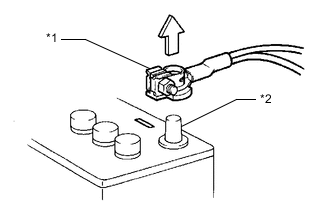
*1 Cable *2 Negative (-) Auxiliary Battery Terminal Note
-
Certain systems need to be initialized after disconnecting and reconnecting the cable to the negative (-) auxiliary battery terminal.
-
Before starting the hybrid system, make sure that the ground point is installed to the body with the bolts.
-
After the power switch is turned off, the navigation receiver assembly records various types of memory and settings. As a result, after turning the power switch off, make sure to wait at least 90 seconds before disconnecting the cable from the negative (-) auxiliary battery terminal.
-
DISCONNECTING AND RECONNECTING NEGATIVE AUXILIARY BATTERY CABLE
-
Before performing work on electronic components, disconnect the cable from the negative (-) auxiliary battery terminal to prevent damage to the electrical system or components.
-
When disconnecting the cable, turn the power switch and headlight switch off and loosen the cable nut completely. Perform these operations without twisting or prying the cable. Then disconnect the cable.
-
Clock settings, radio settings, audio system memory, DTCs and other data will be cleared when the cable is disconnected from the negative (-) auxiliary battery terminal. Write down any necessary data before disconnecting the cable.
-
-
*a INCORRECT HANDLING OF ELECTRONIC PARTS
-
Do not open the cover or case of the ECU unless absolutely necessary. If the IC terminals are touched, the IC may be rendered inoperative by static electricity.
-
Do not pull on the wires when disconnecting electronic connectors. Pull on the connector itself.
-
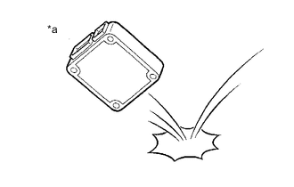
Do not drop electronic components, such as sensors or relays. If they are dropped on a hard surface, they should be replaced.
-
When cleaning the motor room components with steam, protect the electronic components, air filter and emission-related components from water.
-
Never use an impact wrench to remove or install temperature switches or temperature sensors.
-
When measuring the resistance between terminals of a wire connector, insert the tester probe carefully to prevent the terminals from bending.
-
-
-
REMOVING/INSTALLING COMPRESSED HYDROGEN SYSTEM COMPONENTS
CAUTION:
-
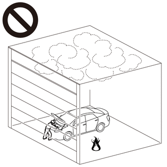
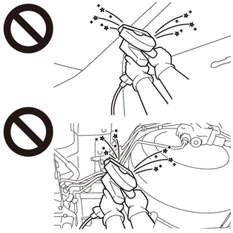
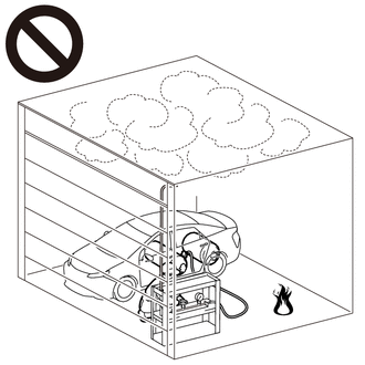
Work procedures must be performed in an area with good ventilation (airflow) where hydrogen gas will not accumulate, and flames or other things that could act as ignition sources must not be present.
-
Accumulated hydrogen gas could ignite, resulting in a serious accident.
-
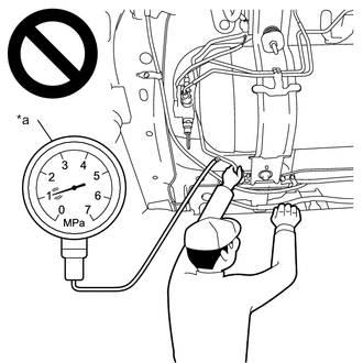
*a When inside of piping is pressurized Do not install or remove any hydrogen system components without first performing depressurization procedures.
-
The highly pressurized hydrogen gas inside the hydrogen tank assembly could blow out, resulting in a serious accident.
-
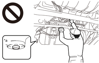
*a Manual Valve Open Do not perform depressurization procedures when the manual valve of the hydrogen tank assembly is open.
-
The highly pressurized hydrogen gas inside the hydrogen tank assembly could blow out, resulting in a serious accident.
-
When performing depressurization, do not perform procedures by hand without wearing protective glasses and gloves.
-
The highly pressurized hydrogen gas inside the hydrogen tank assembly could blow out, resulting in a serious accident.
-
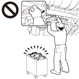
*a After depressurization procedures, the high pressure piping union nut that is loosened first. After performing depressurization procedures, when first loosening the union nut of the high pressure hydrogen piping, do not loosen the union nut by hand without wearing protective glasses and gloves.
-
Even when depressurization procedures are performed, the pressurized hydrogen gas inside the high pressure hydrogen piping cannot be completely depressurized, so the highly pressurized hydrogen gas remaining in the high pressure hydrogen piping could blow out, resulting in a serious accident.
-
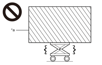
*a Heavy load exceeding the weight limits or size limits of the engine lifter Because the hydrogen tank unit is extremely heavy, make sure to follow the work procedures described in the repair manual.
-
If work is not performed according to the procedures described in the repair manual, there is a danger that the engine lifter could drop and components could fall down.
-
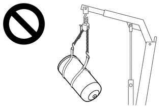
When hoisting up the hydrogen tank assembly, do not hoist it when not properly balanced.
-
The hydrogen tank assembly could fall, resulting in a serious accident.
-
When performing the primary leak inspection, do not perform procedures without wearing protective glasses and gloves.
-
High pressure nitrogen gas could cause a serious accident.
-
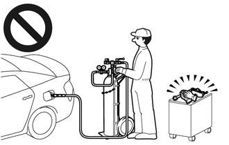
When venting pressurized hydrogen gas from the from the hydrogen tank assembly, do not perform the procedure in an indoor area with poor ventilation.
-
Accumulated hydrogen gas could ignite, resulting in a serious accident.
Note
-
After turning the power switch off, waiting time may be required before disconnecting the cable from the negative (-) auxiliary battery terminal. Therefore, make sure to read the disconnecting the cable from the negative (-) auxiliary battery terminal notices before proceeding with work.
-
Use the "CAUTION: HIGH PRESSURE GAS DO NOT TOUCH" sign to notify other technicians that the high-pressure gas system is being inspected and/or repaired.
*1 Place signs [HIGH PRESSURE GAS WORK IN PROGRESS - DO NOT TOUCH!], etc. to warn other technicians to be cautious. (An example sign is included, so make a copy and use it.) -
When performing depressurization, do not open or close any parts of the hydrogen gas piping except for the following:
- Adjustment bolt of the hydrogen tank assembly manual valve
- Tank shut valve of the hydrogen tank assembly
- Nut of the hydrogen supply regulator assembly medium pressure leak check port
-
When installing or removing hydrogen system components (the hydrogen tank assembly, high pressure hydrogen piping, hydrogen inlet receptacle, hydrogen tube joint, hydrogen tank pressure sensor, and hydrogen supply regulator assembly), to prevent strain such as twisting from being applied to the high pressure hydrogen piping, use the hydrogen tank installation and removal guide tool, and remove the hydrogen tank unit from the vehicle before performing procedures.
-
Even when replacing only the No. 1 hydrogen tank assembly, or only the No. 2 hydrogen tank assembly, to prevent strain from being applied to the high pressure hydrogen piping, use the tank positioning attachment of the hydrogen tank installation and removal tool, and perform positioning of the No. 1 hydrogen tank assembly and No. 2 hydrogen tank assembly.
-
Even when not removing or installing the high pressure hydrogen piping, be careful not to pull or otherwise apply strain to the high pressure hydrogen piping.
-
Do not reuse high pressure hydrogen piping after it has been removed, because the coupling portions will not maintain their airtightness.
-
When reusable parts such as the hydrogen tank assembly valve portion, hydrogen inlet receptacle, hydrogen tube joint and hydrogen supply regulator assembly have been removed, to protect the seal portions and threaded portions from damage as well as to prevent foreign matter such as dust and metal fragments from entering through openings, cover these areas with protective tape.
-
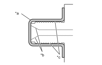
*a Protective Tape *b Seal Portion *c Threaded Portion Do not use use packing tape, or any other tape that will leave residue on parts, as protective tape.
-
Protect seal portions and threaded portions as shown in the illustration.
-
To protect the seal portions and threaded portions from damage or contamination by foreign matter, remove the protective tape immediately before installation.
-
When reassembling components that have been removed, make sure that there is no foreign matter adhering to the openings.
-
After installing hydrogen system components, first perform a primary leak inspection with low pressure nitrogen gas, and then fill pressurized hydrogen gas at a hydrogen station to perform a secondary leak inspection. When performing the secondary leak inspection, the vehicle cannot be driven to the hydrogen station under its own power, so transport it using a car carrier, etc.
-
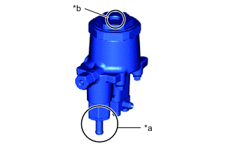
*a Exhaust Tube *b Atmosphere Ventilation Hole Cap Do not insert any sharp objects into the exhaust tube of the hydrogen supply regulator assembly release valve.
-
Do not remove the atmosphere ventilation hole cap of the hydrogen supply regulator assembly.
-
When the vehicle is parked with the power switch off, if the FC control ECU judges that the FC stack temperature will go below 0°C (32°F), it activates the FC air compressor, hydrogen pump and FC cooling water pump for a maximum of 180 seconds and drains water from the FC stack assembly. When performing inspection or repairs with the power switch off (not on (IG) or on (READY)), disconnect the cable from the negative (-) auxiliary battery terminal before performing work.
-
-
REMOVING/INSTALLING FC COOLING SYSTEM COMPONENTS
Note
-
The coolant (Toyota genuine FC stack coolant) is an exclusive coolant.
-
The coolant (Toyota genuine FC stack coolant) cannot be reused, so when filling, be sure to fill with new coolant (Toyota genuine FC stack coolant).
-
To prevent degradation of coolant (Toyota genuine FC stack coolant) performance, do not add or fill any other substances such as tap water or battery electrolyte refill liquid.
-
Do not use cotton work gloves or other gloves that could shed fibers.
-
DO NOT use any container that has previously been used to fill substances such as oil.
-
To prevent foreign matter from contaminating the coolant (Toyota genuine FC stack coolant) passages, wash out the prepared container with tap water, then wipe away any water remaining inside the container before using it.
-
If the coolant (Toyota genuine FC stack coolant) passages are filled incorrectly, follow the countermeasures according to "Countermeasures when coolant (Toyota genuine FC stack coolant) passages are filled incorrectly".
-
When the vehicle is parked with the power switch off, if the FC control ECU judges that the FC stack temperature will go below 0°C (32°F), it activates the FC air compressor, hydrogen pump and FC cooling water pump for a maximum of 180 seconds and drains water from the FC stack assembly. When performing inspection or repairs with the power switch off (not on (IG) or on (READY)), disconnect the cable from the negative (-) auxiliary battery terminal before performing work.
-
If foreign contaminants such as metal fragments enter the cooling system, they will adversely affect the FC stack and other components.
-
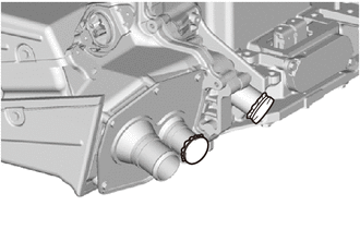
When installing or removing cooling system components, cover the openings of the removed cooling system components as well as the openings of the parts they connect to with protective tape to prevent entry of foreign matter.
-
When installing cooling system components, make sure there is no contamination by foreign matter.
-
-
INSTALLING/REMOVING EV COOLING SYSTEM COMPONENTS
-
If foreign contaminants such as metal fragments enter the cooling system, they will adversely affect the inverter and other components.
-
When installing or removing cooling system components, cover the openings of the removed cooling system components as well as the openings of the parts they connect to with protective tape to prevent entry of foreign matter.
-
When installing cooling system components, make sure there is no contamination by foreign matter.
-
-
REMOVAL AND INSTALLATION OF INTAKE PARTS
-
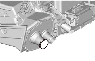
If any metal particles enter intake system parts, they may damage the FC stack.
-
When removing and installing intake system parts, cover the openings of the removed parts and intake system openings. Use adhesive tape or other suitable materials.
-
When installing intake system parts, check that no metal particles have entered the FC stack or installed parts.
-
-
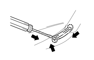
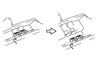
HANDLING OF HOSE CLAMPS
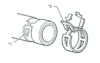
*1 Clamp Track *2 Spring Type Clamp
-
Before removing a hose, check the clamp position so that it can be reinstalled in the same position.
-
Replace any deformed or dented clamps with new ones.
-
When reusing a hose, attach the clamp on the clamp track portion of the hose.
-
For a spring type clamp, it may be necessary to spread the tabs slightly after installation by pushing them in the direction of the arrows as shown in the illustration.
-
-
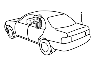
FOR VEHICLES EQUIPPED WITH MOBILE COMMUNICATION SYSTEMS
-
Install the antenna as far away from the ECU and sensors of the vehicle electronic systems as possible.
-
Install the antenna and feeder at least 20 cm (7.87 in.) away from the ECUs and sensors of the vehicle electronic systems. For details about ECU and sensor locations, refer to the section on the applicable components.
-
Keep the antenna and feeder separate from other wiring as much as possible. This will prevent signals sent from the communication equipment from affecting vehicle equipment and vice versa.
-
Check that the antenna and feeder are correctly adjusted.
-
Do not install a high-powered mobile communication system.
-
-
HEADLIGHT INSPECTION OR MAINTENANCE
-
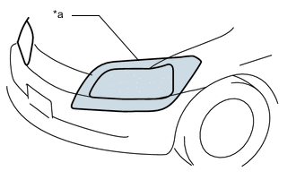
*a Illumination for 3 minutes or more prohibited if covered When the headlights are illuminated, do not cover the headlights for 3 minutes or more.
Note
As the headlight outer lens is made of resin, the resulting heat created when covering the headlight for an extended period of time may deform the headlight.
-
-
FOR VEHICLES EQUIPPED WITH TRACTION CONTROL (TRC) AND VEHICLE STABILITY CONTROL (VSC) SYSTEMS
-
NOTICES FOR WHEN TESTING WITH DRUM TESTER
-
When testing with a 2-wheel drum tester such as a speedometer tester, a combination speedometer and brake tester, or a chassis dynamometer, perform the following procedure to enter inspection mode and disable the TRC and VSC systems.
Note
-
If the vehicle is tested in normal mode on the tester, TRC and VSC operation may cause the vehicle to jump off of the tester.
-
Secure the vehicle with chains for safety.
-
Make sure to cancel inspection mode after completing a check using a 2-wheel drum tester.
-
After performing a check, never drive the vehicle without canceling inspection mode.
Tech Tips
-
During inspection mode, the TRC and VSC systems are disabled and slip indicator light is illuminated.
-
Inspection mode is canceled when the power switch is turned off. As a result, if it is necessary to perform an inspection after the power switch has been turned off, perform the procedure again to re-enter inspection mode.
-
-
-
NOTICES FOR VSC RELATED PROCEDURES
-
For VSC related parts, adjustments are required after removal and installation. Therefore, perform removal and installation only when necessary.
-
When performing VSC related procedures, be sure to strictly follow the preparation and completion procedures.
-
When performing removal and installation or replacement of VSC related parts, first disconnect the cable from the negative (-) auxiliary battery terminal.
-
-
-
WHEN INSPECTING VEHICLES
Note
When operating the vehicle in inspection mode for an operation such as a speedometer test, a DTC may be stored. Therefore, if the warning light comes on, after canceling inspection mode, check for DTCs using the GTS and clear the DTCs.
-
VEHICLE CONDITIONS
-
Activate the appropriate inspection mode and inspect the vehicle.
Tech Tips
Different types of inspection mode are available. One is maintenance mode, and the other is certification mode. The following table indicates the mode appropriate for each test item.
The controls in maintenance mode and certification mode are the same.
Test Item Mode 1. Vehicle straight traveling test (side slip inspection) Maintenance mode or normal mode 2. Braking force test Normal mode 3. Speedometer test Maintenance mode -
Cancel inspection mode immediately after completing the inspection.
Note
Driving the vehicle without canceling inspection mode may damage the transaxle.
-
-
WHEN USING A BRAKE TESTER
Note
-
A high-speed type brake tester cannot be used.
-
Vehicle speed should be less than 0.5 km/h (0.3 mph).
-
Follow all usage and safety procedures in the operator's manual for the brake tester.
-
Place the wheels to be tested (front or rear) onto the rollers.
-
Start the FC system to allow normal brake booster operation.
-
Move the shift lever to N and confirm that neutral (N) has been selected.
-
Operate the brakes to perform the test.
-
-
WHEN USING A SPEEDOMETER TESTER
CAUTION:
Be sure to perform the test in maintenance mode.
Note
Do not perform rapid starting or quick acceleration on a speedometer tester. If rapid starting or quick acceleration is performed on a speedometer tester, damage may occur to the transaxle.
-
Depress the accelerator pedal slowly and gradually accelerate the vehicle, then take a measurement.
-
After the measurement, use the brakes to gradually decelerate the vehicle.
-
-
WHEN USING A CHASSIS DYNAMOMETER
CAUTION:
Be sure to perform the test in maintenance mode.
Note
Sudden acceleration or deceleration of the vehicle on a chassis dynamometer under minimal load may damage the transaxle.
-
Always set an appropriate load before starting the test.
-
-
WHEN USING AN ON-VEHICLE BALANCER
Note
-
Be sure to perform the test in maintenance mode.
-
Start the FC system and then increase the vehicle speed gradually with drive (D) selected.
-
Do not accelerate or decelerate suddenly.
-
Deceleration should be done by braking gradually.
-
Make sure that no one is standing in-line with the spinning wheels.
-
Measurement should be done quickly.
-
Confirm that the vehicle is securely immobilized.
-
Follow all usage and safety procedures in the operator's manual for the wheel balancer.
-
Raise the vehicle until all 4 wheels are off the ground.
-
Support the vehicle with safety stands at an appropriate height. Make sure that the vehicle does not lean in any direction, and that the tires are completely clear of the floor.
-
Place the vibration pick-up unit into position for the wheel to be measured*.
Tech Tips
*: Different on-vehicle wheel balancers have different requirements for mounting the vibration pick-up unit(s). Refer to the operator's manual for the wheel balancer to confirm requirements for use.
-
Release the parking brake.
-
Check that no dragging force exists when turning each wheel by hand.
-
Put the wheel balancer in position.
-
Wheel balance measurement should be done by using both the motor and the wheel balancer drive roller to spin the wheels.
-
-
-
PRECAUTIONS FOR TOWING FRONT WHEEI DRIVE VEHICLES
-
Use one of the following methods to tow the vehicle.
-
If the vehicle has trouble with the chassis or drivetrain, use method 1 (flatbed truck).
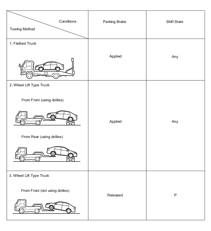
Note
Do not use any towing method other than those shown above.
-
If a tow truck is not available, in an emergency the vehicle may be temporarily towed using a cable or chain secured to the emergency towing eyelet(s). This should only be attempted on hard surfaced roads for as short of a distance as possible and at a vehicle speed of 5 km/h (3 mph) or less.
A driver must be in the vehicle to steer and operate the brakes. The vehicle's wheels, drivetrain, axles, steering and brakes must be in good condition.
Note
If the towing speed exceeds the above limits, or if the vehicle is towed for a long distance or in a backward direction with any of the wheels on the ground, the drivetrain may be damaged.
-
Emergency towing procedure
-
Turn the power switch on (IG).
-
Depress the brake pedal and move the shift lever to N.
-
Release the parking brake.
-
Release the brake pedal slowly.
Note
-
Use extreme caution when towing the vehicle. Avoid sudden starts or erratic driving maneuvers which place excessive stress on the emergency towing eyelet and the cables or chains.
Tech Tips
-
Neutral (N) cannot be selected if the auxiliary battery is discharged or if it has been disconnected.
-
There is a possibility that neutral (N) cannot be selected when parts related to the transmission control ECU have a malfunction.
-
-
-
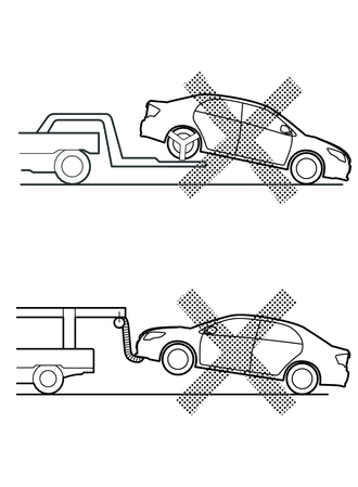
The towing methods shown below are dangerous and can damage the vehicle, so do not use them.
-
Do not tow the vehicle with only 2 wheels on the ground.
Note
If the vehicle is towed with only 2 wheels on the ground, the drivetrain may overheat and be damaged, or the wheels may come off the dollies.
-
Do not use a sling-type towing method either from the front or rear.
Note
If a sling-type tow truck is used, damage may occur to the vehicle body.
-
-