ENGINE UNIT REMOVAL

CAUTION / NOTICE / HINT
CAUTION:
-
The exhaust valve is filled with sodium. Sodium is a strong alkali which may produce a dangerous chemical reaction. Therefore, be very careful when handling and disposing of it.
-
Do not disassemble the exhaust valve for the following reasons: 1) If sodium enters your eyes, vision loss may occur. 2) If sodium contacts your skin, burns may occur. 3) If sodium is exposed to a flame and starts a fire due to the chemical reaction that takes place, burns may occur.
-
If the exhaust valve is damaged, remove the valve and perform the proper procedures to dispose of the sodium. (disposal preparation and actual disposal)
-
When removing a damaged exhaust valve, always wear rubber gloves and safety glasses.
-
Do not cut the exhaust valve to take out the sodium.
Tech Tips
-
The sodium inside the exhaust valve is safe as long as the sodium is not exposed to air.
-
Exhaust valves filled with sodium can be identified by confirming the "NA" identification mark.
-
Remove the exhaust valve.
-
Dispose of exhaust valve.
PROCEDURE
-
REMOVE FAN AND GENERATOR V BELT
-
REMOVE GENERATOR ASSEMBLY
-
REMOVE COMPRESSOR ASSEMBLY WITH PULLEY
-
REMOVE NO. 1 COMPRESSOR MOUNTING BRACKET
-
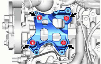
Remove the 2 bolts, 2 nuts and No. 1 compressor mounting bracket.
-
Remove the 2 stud bolts from the cylinder block sub-assembly and stiffening crankcase assembly.
-
-
REMOVE NO. 2 WATER BY-PASS PIPE
-
REMOVE PURGE VSV
-
DISCONNECT NO. 2 VACUUM TRANSMITTING HOSE ASSEMBLY
-
DISCONNECT VACUUM TRANSMITTING HOSE ASSEMBLY
-
DISCONNECT NO. 1 AND NO. 2 WATER BY-PASS HOSE
-
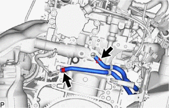
Slide the clamp and disconnect the No. 1 water by-pass hose from the cylinder head sub-assembly.
-
Slide the clamp and disconnect the No. 2 water by-pass hose from the No. 1 water by-pass pipe.
-
-
REMOVE NO. 2 PCV HOSE
-
REMOVE INTAKE MANIFOLD WITH INTERCOOLER ASSEMBLY AND THROTTLE WITH MOTOR BODY ASSEMBLY
-
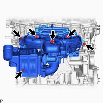
Remove the 4 bolts, 2 nuts and intake manifold with intercooler assembly and throttle with motor body assembly.
-
Remove the 2 No. 1 intake manifold to head gaskets from the intake manifold.
-
-
REMOVE IGNITION COIL ASSEMBLY
-
REMOVE NO. 1 EXHAUST MANIFOLD HEAT INSULATOR
-
REMOVE NO. 2 EXHAUST MANIFOLD HEAT INSULATOR
-
REMOVE EXHAUST MANIFOLD CONVERTER SUB-ASSEMBLY
-
DISCONNECT TURBO OIL INLET PIPE SUB-ASSEMBLY
-
REMOVE TURBOCHARGER SUB-ASSEMBLY
-
REMOVE ENGINE WIRE
-
REMOVE WIRE HARNESS CLAMP BRACKET
-
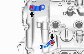
for Engine Upper Side:
Remove the 2 bolts and 2 wire harness clamp brackets from the cylinder head cover sub-assembly.
-

for Engine Rear Side:
Remove the 3 bolts and 3 wire harness clamp brackets from the cylinder head sub-assembly.
-
-
REMOVE OIL FILLER CAP SUB-ASSEMBLY
-
Remove the oil filler cap sub-assembly from the cylinder head cover sub-assembly.
-
-
REMOVE OIL FILLER CAP GASKET
-
Remove the oil filler cap gasket from the oil filler cap sub-assembly.
-
-
REMOVE IDLER PULLEY SUB-ASSEMBLY
-
REMOVE V-RIBBED BELT TENSIONER ASSEMBLY
-
REMOVE NO. 8 ENGINE WIRE