THROTTLE BODY INSTALLATION
CAUTION / NOTICE / HINT
Note
This procedure includes the removal of small-head bolts. Refer to Small-Head Bolts of Basic Repair Hint to identify the small-head bolts.
Tech Tips
Perform "Inspection After Repairs" after replacing the throttle body with motor assembly.
-
w/ Canister Pump Module:
-
w/o Canister Pump Module:
PROCEDURE
-
INSTALL THROTTLE BODY WITH MOTOR ASSEMBLY (for Bank 2)
Tech Tips
Perform "Inspection After Repairs" after replacing the throttle body with motor assembly.
-
w/ Canister Pump Module:
-
w/o Canister Pump Module:
-
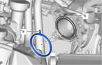
*a Protrusion *b Groove Install a new gasket to the intake air surge tank assembly with intercooler with the protrusion of the gasket.
-
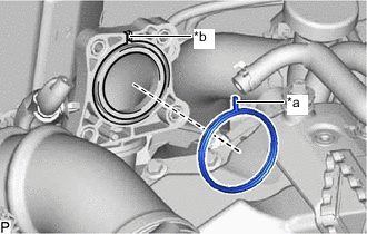
*a Protrusion *b Groove Install a new gasket to the No. 2 air tube assembly with the protrusion of the gasket.
-
Connect the No. 4 water by-pass hose to the throttle body with motor assembly and slide the clip to secure the hose.
-
Connect the No. 6 water by-pass hose to the throttle body with motor assembly and slide the clip to secure the hose.
-
Install the throttle body with motor assembly and No. 2 air tube assembly to the intake air surge tank assembly with intercooler with the 4 bolts.
- Torque:
- 10 N*m { 102 kgf*cm, 7 ft.*lbf }
-
Connect the throttle body with motor assembly connector.
-
Install the bolt.
- Torque:
- 10 N*m { 102 kgf*cm, 7 ft.*lbf }
-
Attach the 3 wire harness clamps.
-
Install the bolt.
- Torque:
- 10 N*m { 102 kgf*cm, 7 ft.*lbf }
-
-
INSTALL THROTTLE BODY WITH MOTOR ASSEMBLY (for Bank 1)
Tech Tips
Perform "Inspection After Repairs" after replacing the throttle body with motor assembly.
-
w/ Canister Pump Module:
-
w/o Canister Pump Module:
-
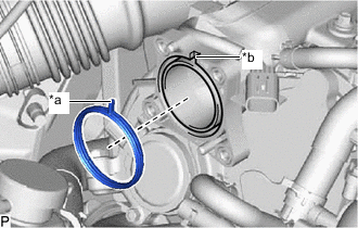
*a Protrusion *b Groove Install a new gasket to the intake air surge tank assembly with intercooler with the protrusion of the gasket.
-
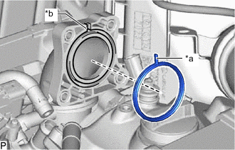
*a Protrusion *b Groove Install a new gasket to the No. 1 air tube assembly with the protrusion of the gasket.
-
Connect the No. 3 water by-pass hose to the throttle body with motor assembly and slide the clip to secure the hose.
-
Connect the No. 5 water by-pass hose to the throttle body with motor assembly and slide the clip to secure the hose.
-
Install the throttle body with motor assembly and No. 1 air tube assembly to the intake air surge tank assembly with intercooler with the 4 bolts.
- Torque:
- 10 N*m { 102 kgf*cm, 7 ft.*lbf }
-
Connect the throttle body with motor assembly connector.
-
Install the bolt.
- Torque:
- 10 N*m { 102 kgf*cm, 7 ft.*lbf }
-
Attach the 3 wire harness clamps.
-
Install the bolt.
- Torque:
- 10 N*m { 102 kgf*cm, 7 ft.*lbf }
-
-
INSTALL NO. 2 AIR TUBE ASSEMBLY
-
Connect the No. 2 air tube assembly with the clip and clamp.
- Torque:
- 6.3 N*m { 64 kgf*cm, 56 in.*lbf }
-
Connect the No. 2 air tube connector.
-
Connect the No. 5 air hose to the No. 1 turbo pressure sensor and slide the clip to secure the hose.
-
Connect the wire harness with the 2 bolts.
- Torque:
- 10 N*m { 102 kgf*cm, 7 ft.*lbf }
-
-
INSTALL NO. 1 AIR TUBE ASSEMBLY
-
Connect the No. 1 air tube assembly with the clip and clamp.
- Torque:
- 6.3 N*m { 64 kgf*cm, 56 in.*lbf }
-
Connect the No. 1 air tube connector.
-
Connect the No. 4 air hose to the No. 1 turbo pressure sensor and slide the clip to secure the hose.
-
Connect the wire harness with the 2 bolts.
- Torque:
- 10 N*m { 102 kgf*cm, 7 ft.*lbf }
-
-
ADD ENGINE COOLANT
-
INSPECT FOR COOLANT LEAK
-
INSTALL AIR CLEANER ASSEMBLY LH
-
INSTALL AIR CLEANER ASSEMBLY RH
-
INSTALL RADIATOR SUPPORT TO CROSSMEMBER BRACE SUB-ASSEMBLY LH
-
INSTALL RADIATOR SUPPORT TO CROSSMEMBER BRACE SUB-ASSEMBLY RH
-
INSTALL LOWER RADIATOR AIR DEFLECTOR
-
INSTALL UPPER RADIATOR SUPPORT SEAL
-
INSTALL RADIATOR COVER PLATE
-
INSTALL V-BANK COVER SUB-ASSEMBLY