SFI SYSTEM, Diagnostic DTC:P245211
| DTC Code | DTC Name |
|---|---|
| P245211 | Particulate Filter Pressure Sensor "A" Circuit Short to Ground |
DESCRIPTION
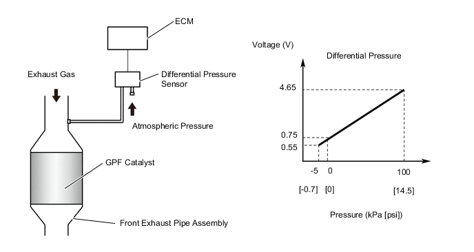
A differential pressure sensor is installed to monitor the pressure before the GPF (Gasoline Particulate Filter) catalyst converter. The sensor is a semiconductor type that is not affected by the exhaust gas. The differential pressure sensor outputs the difference between the atmospheric pressure and the pressure before the GPF catalyst.
| DTC No. | Detection Item | DTC Detection Condition | Trouble Area | MIL | Memory | Note |
|---|---|---|---|---|---|---|
| P245211 | Particulate Filter Pressure Sensor "A" Circuit Short to Ground | The output voltage from the differential pressure sensor is below 0.4 V for 3 seconds or more (1 trip detection logic). |
|
Does not come on | DTC stored | SAE: P2454 |
Tech Tips
When a DTC is output, check the Data List item "GPF Differential Pressure Sensor Bank 1 using the GTS.
| DTC No. | GPF Differential Pressure Sensor Bank 1 | Malfunction |
|---|---|---|
| P245211 | Approximately -5 kPa [-0.73 psi] |
|
If the Data List displays a normal value, the normal value may be due to a temporary recovery from the malfunction condition. Check for intermittent problems.
MONITOR DESCRIPTION
In order to detect abnormality in the differential pressure sensor, the ECM always monitors the output voltage from the sensor. When the sensor output voltage deviates from the normal operating range, the ECM interprets this as a malfunction in the sensor circuit and illuminates the MIL.
Example:
When the sensor output voltage is below 0.4 V for 3 seconds or more, the ECM stores a DTC.
MONITOR STRATEGY
| Frequency of Operation | Continuous |
CONFIRMATION DRIVING PATTERN
-
Connect the GTS to the DLC3.
-
Turn the ignition switch to ON.
-
Turn the GTS on.
-
Clear the DTCs (even if no DTCs are stored, perform the clear DTC procedure).
-
Turn the ignition switch off and wait for at least 30 seconds.
-
Turn the ignition switch to ON.
-
Turn the GTS on.
-
Start the engine and wait 5 seconds or more.
-
Enter the following menus: Powertrain / Engine / Trouble Codes.
-
Read the pending DTCs.
Tech Tips
-
If a pending DTC is output, the system is malfunctioning.
-
If a pending DTC is not output, perform the following procedure.
-
-
Enter the following menus: Powertrain / Engine / Utility / All Readiness.
-
Input the DTC: P245211.
-
Check the DTC judgment result.
GTS Display Description NORMAL
-
DTC judgment completed
-
System normal
ABNORMAL
-
DTC judgment completed
-
System abnormal
INCOMPLETE
-
DTC judgment not completed
-
Perform driving pattern after confirming DTC enabling conditions
Tech Tips
-
If the judgment result shows NORMAL, the system is normal.
-
If the judgment result shows ABNORMAL, the system has a malfunction.
-
WIRING DIAGRAM
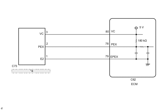
| *a | Differential Pressure Sensor |
CAUTION / NOTICE / HINT
Tech Tips
Read Freeze Frame Data using the GTS. The ECM records vehicle and driving condition information as Freeze Frame Data the moment a DTC is stored. When troubleshooting, Freeze Frame Data can help determine if the vehicle was moving or stationary, if the engine was warmed up or not, if the air fuel ratio was lean or rich, and other data from the time the malfunction occurred.
PROCEDURE
-
CHECK TERMINAL VOLTAGE (DIFFERENTIAL PRESSURE SENSOR)
Tech Tips
Make sure that the connector is properly connected. If it is not, securely connect it and check for DTCs again.
-
Disconnect the C73 differential pressure sensor connector.
-
Turn the ignition switch to ON.
-
Measure the voltage according to the value(s) in the table below.
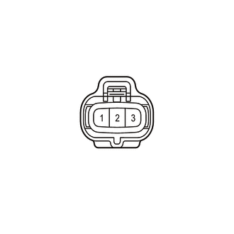
Tester Connection Switch Condition Specified Condition C73-3 (VC) - C73-1 (E2) Ignition switch ON 4.5 to 5.5 V C73-2 (PEX) - C73-1 (E2) Ignition switch ON 0.5 to 3.0 V -
Turn the ignition switch off and wait for at least 30 seconds.
-
Measure the voltage according to the value(s) in the table below.
Tester Connection Switch Condition Specified Condition C73-3 (VC) - C73-2 (PEX) Ignition switch off 171 to 189 kΩ Result Proceed to OK NG
OK 
REPLACE DIFFERENTIAL PRESSURE SENSOR Click here
NG 
-
-
CHECK HARNESS AND CONNECTOR (DIFFERENTIAL PRESSURE SENSOR - ECM)
-
Disconnect the C73 differential pressure sensor connector.
-
Disconnect the C62 ECM connector.
-
Measure the voltage according to the value(s) in the table below.
Tester Connection Condition Specified Condition C73-3 (VC) - C62-80 (VC) Always Below 1 Ω C73-2 (PEX) or C62-78 (PEX) - Body ground and other terminals Always 10 kΩ or higher Result Proceed to OK NG
OK
REPLACE ECM Click here
NG
REPAIR OR REPLACE HARNESS OR CONNECTOR
-