NAVIGATION SYSTEM, Diagnostic DTC:B15C3
| DTC Code | DTC Name |
|---|---|
| B15C3 | Speaker Output Short |
DESCRIPTION
This DTC is stored when a malfunction occurs in the speakers.
In addition, the radio receiver assembly detects a malfunction via the stereo component amplifier assembly.
| DTC No. | Detection Item | DTC Detection Condition | Trouble Area |
|---|---|---|---|
| B15C3 | Speaker Output Short | A short is detected in the speaker output circuit |
|
WIRING DIAGRAM
CAUTION / NOTICE / HINT
Note
When replacing the DCM (telematics transceiver), make sure to replace it with a new one (w/ Telematics Transceiver [for ERA-GLONASS] or w/ Telematics Transceiver [for G-BOOK]).
Tech Tips
Depending on the parts that are replaced during vehicle inspection or maintenance, performing initialization, registration or calibration may be needed. Refer to Precaution for Navigation System.
PROCEDURE
-
CHECK DTC
-
Clear the DTCs.
Body Electrical > Navigation System > Clear DTCs -
Recheck for DTCs and check that no DTCs are output.
Body Electrical > Navigation System > Trouble CodesOK No DTCs are output. Result Proceed to OK NG
OK 
USE SIMULATION METHOD TO CHECK Click here
NG 
-
-
CHECK VEHICLE TYPE
-
Check the vehicle type.
Result Result Proceed to for 12 Speakers A for 23 Speakers B
B 
CHECK HARNESS AND CONNECTOR (SPEAKER CIRCUIT) Click here
A
-
-
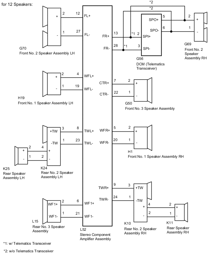
CHECK HARNESS AND CONNECTOR (SPEAKER CIRCUIT)
-
*1: for LH Side
*2: for RH Side
*3: w/ Telematics Transceiver
-
Disconnect the L52 stereo component amplifier assembly connector.
-
Disconnect the H19*1 and/or H1*2 front No. 1 speaker assembly connector.
-
Disconnect the G70*1 and/or G69*2 front No. 2 speaker assembly connector.
-
Disconnect the G50 front No. 3 speaker assembly connector.
-
Disconnect the K25*1 and/or K11*2 rear speaker assembly connector.
-
Disconnect the K24*1 and/or K10*2 rear No. 2 speaker assembly connector.
-
Disconnect the L15 rear No. 3 speaker assembly connector.
-
Disconnect the G56 DCM (telematics transceiver) connector.*3
-
Measure the resistance according to the value(s) in the table below.
Standard Resistance for LH Side: Tester Connection Condition Specified Condition L52-4 (WFL+) - H19-2 (+) Always Below 1 Ω L52-19 (WFL-) - H19-1 (-) Always Below 1 Ω L52-12 (FL+) - G70-2 (+) Always Below 1 Ω L52-27 (FL-) - G70-1 (-) Always Below 1 Ω L52-8 (TWL+) - K24-3 (+TW) Always Below 1 Ω L52-23 (TWL-) - K24-1 (-TW) Always Below 1 Ω K24-4 (+) - K25-2 (+) Always Below 1 Ω K24-2 (-) - K25-1 (-) Always Below 1 Ω L52-4 (WFL+) - Body ground Always 10 kΩ or higher L52-19 (WFL-) - Body ground Always 10 kΩ or higher L52-12 (FL+) - Body ground Always 10 kΩ or higher L52-27 (FL-) - Body ground Always 10 kΩ or higher L52-8 (TWL+) - Body ground Always 10 kΩ or higher L52-23 (TWL-) - Body ground Always 10 kΩ or higher K24-4 (+) - Body ground Always 10 kΩ or higher K24-2 (-) - Body ground Always 10 kΩ or higher for RH Side (w/ Telematics Transceiver): Tester Connection Condition Specified Condition L52-5 (WFR+) - H1-2 (+) Always Below 1 Ω L52-20 (WFR-) - H1-1 (-) Always Below 1 Ω L52-13 (FR+) - G56-2 (SPI+) Always Below 1 Ω L52-28 (FR-) - G56-3 (SPI-) Always Below 1 Ω G56-5 (SPO+) - G69-2 (+) Always Below 1 Ω G56-6 (SPO-) - G69-1 (-) Always Below 1 Ω L52-9 (TWR+) - K10-3 (+TW) Always Below 1 Ω L52-24 (TWR-) - K10-1 (-TW) Always Below 1 Ω K10-4 (+) - K11-2 (+) Always Below 1 Ω K10-2 (-) - K11-1 (-) Always Below 1 Ω L52-5 (WFR+) - Body ground Always 10 kΩ or higher L52-20 (WFR-) - Body ground Always 10 kΩ or higher L52-13 (FR+) - Body ground Always 10 kΩ or higher L52-28 (FR-) - Body ground Always 10 kΩ or higher G56-5 (SPO+) - Body ground Always 10 kΩ or higher G56-6 (SPO-) - Body ground Always 10 kΩ or higher L52-9 (TWR+) - Body ground Always 10 kΩ or higher L52-24 (TWR-) - Body ground Always 10 kΩ or higher K10-4 (+) - Body ground Always 10 kΩ or higher K10-2 (-) - Body ground Always 10 kΩ or higher for RH Side (w/o Telematics Transceiver): Tester Connection Condition Specified Condition L52-5 (WFR+) - H1-2 (+) Always Below 1 Ω L52-20 (WFR-) - H1-1 (-) Always Below 1 Ω L52-13 (FR+) - G69-2 (+) Always Below 1 Ω L52-28 (FR-) - G69-1 (-) Always Below 1 Ω L52-9 (TWR+) - K10-3 (+TW) Always Below 1 Ω L52-24 (TWR-) - K10-1 (-TW) Always Below 1 Ω K10-4 (+) - K11-2 (+) Always Below 1 Ω K10-2 (-) - K11-1 (-) Always Below 1 Ω L52-5 (WFR+) - Body ground Always 10 kΩ or higher L52-20 (WFR-) - Body ground Always 10 kΩ or higher L52-13 (FR+) - Body ground Always 10 kΩ or higher L52-28 (FR-) - Body ground Always 10 kΩ or higher L52-9 (TWR+) - Body ground Always 10 kΩ or higher L52-24 (TWR-) - Body ground Always 10 kΩ or higher K10-4 (+) - Body ground Always 10 kΩ or higher K10-2 (-) - Body ground Always 10 kΩ or higher for Center Side: Tester Connection Condition Specified Condition L52-7 (CTR+) - G50-2 (+) Always Below 1 Ω L52-22 (CTR-) - G50-1 (-) Always Below 1 Ω L52-6 (WF1+) - L15-2 (+) Always Below 1 Ω L52-21 (WF1-) - L15-1 (-) Always Below 1 Ω L52-7 (CTR+) - Body ground Always 10 kΩ or higher L52-22 (CTR-) - Body ground Always 10 kΩ or higher L52-6 (WF1+) - Body ground Always 10 kΩ or higher L52-21 (WF1-) - Body ground Always 10 kΩ or higher Result Proceed to OK NG
NG
REPAIR OR REPLACE HARNESS OR CONNECTOR
OK
-
-
INSPECT FRONT NO. 3 SPEAKER ASSEMBLY
-
Remove the front No. 3 speaker assembly.
-
Inspect the front No. 3 speaker assembly.
Result Proceed to OK NG
NG
REPLACE FRONT NO. 3 SPEAKER ASSEMBLY Click here
OK
-
-
INSPECT FRONT NO. 1 SPEAKER ASSEMBLY
-
Remove the front No. 1 speaker assembly.
-
Inspect the front No. 1 speaker assembly.
Result Proceed to OK NG
NG
REPLACE FRONT NO. 1 SPEAKER ASSEMBLY Click here
OK
-
-
INSPECT REAR SPEAKER ASSEMBLY
-
Remove the rear speaker assembly.
-
Inspect the rear speaker assembly.
Result Proceed to OK NG
NG
REPLACE REAR SPEAKER ASSEMBLY Click here
OK
-
-
INSPECT REAR NO. 3 SPEAKER ASSEMBLY
-
Remove the rear No. 3 speaker assembly.
-
Inspect the rear No. 3 speaker assembly.
Result Proceed to OK NG
NG
REPLACE REAR NO. 3 SPEAKER ASSEMBLY Click here
OK
-
-
CHECK VEHICLE TYPE
-
Check the vehicle type.
Result Result Proceed to w/ Telematics Transceiver A w/o Telematics Transceiver B
B
GO TO STEP 10 Click here
A
-
-
INSPECT DCM (TELEMATICS TRANSCEIVER) (SPO+, SPO-, SPI+, SPI-)
-
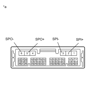
*a Component without harness connected
(DCM [Telematics Transceiver])
Remove the DCM (telematics transceiver).
-
Measure the resistance according to the value(s) in the table below.
Standard Resistance Tester Connection Condition Specified Condition 5 (SPO+) - 2 (SPI+) Always Below 1 Ω 6 (SPO-) - 3 (SPI-) Always Below 1 Ω 5 (SPO+) - Body ground Always 10 kΩ or higher 6 (SPO-) - Body ground Always 10 kΩ or higher 2 (SPI+) - 3 (SPI-) Always 10 kΩ or higher 5 (SPO+) - 6 (SPO-) Always 10 kΩ or higher Result Proceed to OK NG
NG
REPLACE DCM (TELEMATICS TRANSCEIVER) Click here
OK
-
-
CHECK FRONT NO. 2 SPEAKER ASSEMBLY
-
Replace the front No. 2 speaker assembly with a new or known good one.
-
Clear the DTCs.
Body Electrical > Navigation System > Clear DTCs -
Recheck for DTCs and check that no DTCs are output.
Body Electrical > Navigation System > Trouble CodesOK No DTCs are output. Result Proceed to OK NG
OK
END (FRONT NO. 2 SPEAKER ASSEMBLY IS DEFECTIVE)
NG
-
-
CHECK REAR NO. 2 SPEAKER ASSEMBLY
-
Replace the rear No. 2 speaker assembly with a new or known good one.
-
Clear the DTCs.
Body Electrical > Navigation System > Clear DTCs -
Recheck for DTCs and check that no DTCs are output.
Body Electrical > Navigation System > Trouble CodesOK No DTCs are output. Result Proceed to OK NG
OK
END (REAR NO. 2 SPEAKER ASSEMBLY IS DEFECTIVE)
NG
REPLACE STEREO COMPONENT AMPLIFIER ASSEMBLY Click here
-
-
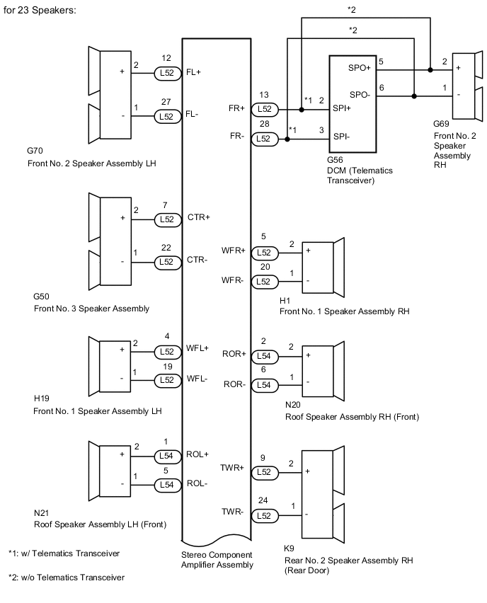
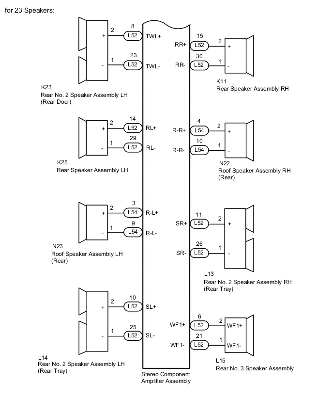
CHECK HARNESS AND CONNECTOR (SPEAKER CIRCUIT)
-
*1: for LH Side
*2: for RH Side
*3: w/ Telematics Transceiver
-
Disconnect the L52 and L54 stereo component amplifier assembly connector.
-
Disconnect the H19*1 and/or H1*2 front No. 1 speaker assembly connector.
-
Disconnect the G70*1 and/or G69*2 front No. 2 speaker assembly connector.
-
Disconnect the G50 front No. 3 speaker assembly connector.
-
Disconnect the N21*1 and/or N20*2 roof speaker assembly (front) connector.
-
Disconnect the K25*1 and/or K11*2 rear speaker assembly connector.
-
Disconnect the K23*1 and/or K9*2 rear No. 2 speaker assembly (rear door) connector.
-
Disconnect the N23*1 and/or N22*2 roof speaker assembly (rear) connector.
-
Disconnect the L14*1 and/or L13*2 rear No. 2 speaker assembly (rear tray) connector.
-
Disconnect the L15 rear No. 3 speaker assembly connector.
-
Disconnect the G56 DCM (telematics transceiver) connector.*3
-
Measure the resistance according to the value(s) in the table below.
Standard Resistance for LH Side: Tester Connection Condition Specified Condition L52-4 (WFL+) - H19-2 (+) Always Below 1 Ω L52-19 (WFL-) - H19-1 (-) Always Below 1 Ω L52-12 (FL+) - G70-2 (+) Always Below 1 Ω L52-27 (FL-) - G70-1 (-) Always Below 1 Ω L52-8 (TWL+) - K23-2 (+) Always Below 1 Ω L52-23 (TWL-) - K23-1 (-) Always Below 1 Ω L54-1 (ROL+) - N21-2 (+) Always Below 1 Ω L54-5 (ROL-) - N21-1 (-) Always Below 1 Ω L52-14 (RL+) - K25-2 (+) Always Below 1 Ω L52-29 (RL-) - K25-1 (-) Always Below 1 Ω L54-3 (R-L+) - N23-2 (+) Always Below 1 Ω L54-9 (R-L-) - N23-1 (-) Always Below 1 Ω L52-10 (SL+) - L14-2 (+) Always Below 1 Ω L52-25 (SL-) - L14-1 (-) Always Below 1 Ω L52-4 (WFL+) - Body ground Always 10 kΩ or higher L52-19 (WFL-) - Body ground Always 10 kΩ or higher L52-12 (FL+) - Body ground Always 10 kΩ or higher L52-27 (FL-) - Body ground Always 10 kΩ or higher L52-8 (TWL+) - Body ground Always 10 kΩ or higher L52-23 (TWL-) - Body ground Always 10 kΩ or higher L54-1 (ROL+) - Body ground Always 10 kΩ or higher L54-5 (ROL-) - Body ground Always 10 kΩ or higher L52-14 (RL+) - Body ground Always 10 kΩ or higher L52-29 (RL-) - Body ground Always 10 kΩ or higher L54-3 (R-L+) - Body ground Always 10 kΩ or higher L54-9 (R-L-) - Body ground Always 10 kΩ or higher L52-10 (SL+) - Body ground Always 10 kΩ or higher L52-25 (SL-) - Body ground Always 10 kΩ or higher for RH Side (w/ Telematics Transceiver): Tester Conne ction Condition Specified Condition L52-5 (WFR+) - H1-2 (+) Always Below 1 Ω L52-20 (WFR-) - H1-1 (-) Always Below 1 Ω L52-13 (FR+) - G56-2 (SPI+) Always Below 1 Ω L52-28 (FR-) - G56-3 (SPI-) Always Below 1 Ω G56-5 (SPO+) - G69-2 (+) Always Below 1 Ω G56-6 (SPO-) - G69-1 (-) Always Below 1 Ω L52-9 (TWR+) - K9-2 (+) Always Below 1 Ω L52-24 (TWR-) - K9-1 (-) Always Below 1 Ω L54-2 (ROR+) - N20-2 (+) Always Below 1 Ω L54-6 (ROR-) - N20-1 (-) Always Below 1 Ω L52-15 (RR+) - K11-2 (+) Always Below 1 Ω L52-30 (RR-) - K11-1 (-) Always Below 1 Ω L54-4 (R-R+) - N22-2 (+) Always Below 1 Ω L54-10 (R-R-) - N22-1 (-) Always Below 1 Ω L52-11 (SR+) - L13-2 (+) Always Below 1 Ω L52-26 (SR-) - L13-1 (-) Always Below 1 Ω L52-5 (WFR+) - Body ground Always 10 kΩ or higher L52-20 (WFR-) - Body ground Always 10 kΩ or higher L52-13 (FR+) - Body ground Always 10 kΩ or higher L52-28 (FR-) - Body ground Always 10 kΩ or higher G56-5 (SPO+) - Body ground Always 10 kΩ or higher G56-6 (SPO-) - Body ground Always 10 kΩ or higher L52-9 (TWR+) - Body ground Always 10 kΩ or higher L52-24 (TWR-) - Body ground Always 10 kΩ or higher L54-2 (ROR+) - Body ground Always 10 kΩ or higher L54-6 (ROR-) - Body ground Always 10 kΩ or higher L52-15 (RR+) - Body ground Always 10 kΩ or higher L52-30 (RR-) - Body ground Always 10 kΩ or higher L54-4 (R-R+) - Body ground Always 10 kΩ or higher L54-10 (R-R-) - Body ground Always 10 kΩ or higher L52-11 (SR+) - Body ground Always 10 kΩ or higher L52-26 (SR-) - Body ground Always 10 kΩ or higher for RH Side (w/o Telematics Transceiver): Tester Conne ction Condition Specified Condition L52-5 (WFR+) - H1-2 (+) Always Below 1 Ω L52-20 (WFR-) - H1-1 (-) Always Below 1 Ω L52-13 (FR+) - G69-2 (+) Always Below 1 Ω L52-28 (FR-) - G69-1 (-) Always Below 1 Ω L52-9 (TWR+) - K9-2 (+) Always Below 1 Ω L52-24 (TWR-) - K9-1 (-) Always Below 1 Ω L54-2 (ROR+) - N20-2 (+) Always Below 1 Ω L54-6 (ROR-) - N20-1 (-) Always Below 1 Ω L52-15 (RR+) - K11-2 (+) Always Below 1 Ω L52-30 (RR-) - K11-1 (-) Always Below 1 Ω L54-4 (R-R+) - N22-2 (+) Always Below 1 Ω L54-10 (R-R-) - N22-1 (-) Always Below 1 Ω L52-11 (SR+) - L13-2 (+) Always Below 1 Ω L52-26 (SR-) - L13-1 (-) Always Below 1 Ω L52-5 (WFR+) - Body ground Always 10 kΩ or higher L52-20 (WFR-) - Body ground Always 10 kΩ or higher L52-13 (FR+) - Body ground Always 10 kΩ or higher L52-28 (FR-) - Body ground Always 10 kΩ or higher L52-9 (TWR+) - Body ground Always 10 kΩ or higher L52-24 (TWR-) - Body ground Always 10 kΩ or higher L54-2 (ROR+) - Body ground Always 10 kΩ or higher L54-6 (ROR-) - Body ground Always 10 kΩ or higher L52-15 (RR+) - Body ground Always 10 kΩ or higher L52-30 (RR-) - Body ground Always 10 kΩ or higher L54-4 (R-R+) - Body ground Always 10 kΩ or higher L54-10 (R-R-) - Body ground Always 10 kΩ or higher L52-11 (SR+) - Body ground Always 10 kΩ or higher L52-26 (SR-) - Body ground Always 10 kΩ or higher for Center Side: Tester Connection Condition Specified Condition L52-7 (CTR+) - G50-2 (+) Always Below 1 Ω L52-22 (CTR-) - G50-1 (-) Always Below 1 Ω L52-6 (WF1+) - L15-2 (+) Always Below 1 Ω L52-21 (WF1-) - L15-1 (-) Always Below 1 Ω L52-7 (CTR+) - Body ground Always 10 kΩ or higher L52-22 (CTR-) - Body ground Always 10 kΩ or higher L52-6 (WF1+) - Body ground Always 10 kΩ or higher L52-21 (WF1-) - Body ground Always 10 kΩ or higher Result Proceed to OK NG
NG
REPAIR OR REPLACE HARNESS OR CONNECTOR
OK
-
-
INSPECT FRONT NO. 1 SPEAKER ASSEMBLY
-
Remove the front No. 1 speaker assembly.
-
Inspect the front No. 1 speaker assembly.
Result Proceed to OK NG
NG
REPLACE FRONT NO. 1 SPEAKER ASSEMBLY Click here
OK
-
-
INSPECT ROOF SPEAKER ASSEMBLY (FRONT)
-
Remove the roof speaker assembly (front).
-
Inspect the roof speaker assembly (front).
Result Proceed to OK NG
NG
REPLACE ROOF SPEAKER ASSEMBLY (FRONT) Click here
OK
-
-
INSPECT ROOF SPEAKER ASSEMBLY (REAR)
-
Remove the roof speaker assembly (rear).
-
Inspect the roof speaker assembly (rear).
Result Proceed to OK NG
NG
REPLACE ROOF SPEAKER ASSEMBLY (REAR) Click here
OK
-
-
INSPECT REAR SPEAKER ASSEMBLY
-
Remove the rear speaker assembly.
-
Inspect the rear speaker assembly.
Result Proceed to OK NG
NG
REPLACE REAR SPEAKER ASSEMBLY Click here
OK
-
-
INSPECT REAR NO. 3 SPEAKER ASSEMBLY
-
Remove the rear No. 3 speaker assembly.
-
Inspect the rear No. 3 speaker assembly.
Result Proceed to OK NG
NG
REPLACE REAR NO. 3 SPEAKER ASSEMBLY Click here
OK
-
-
CHECK VEHICLE TYPE
-
Check the vehicle type.
Result Result Proceed to w/ Telematics Transceiver A w/o Telematics Transceiver B
B
GO TO STEP 20 Click here
A
-
-
INSPECT DCM (TELEMATICS TRANSCEIVER) (SPO+, SPO-, SPI+, SPI-)
-
*a Component without harness connected
(DCM [Telematics Transceiver])
Remove the DCM (telematics transceiver).
-
Measure the resistance according to the value(s) in the table below.
Standard Resistance Tester Connection Condition Specified Condition 5 (SPO+) - 2 (SPI+) Always Below 1 Ω 6 (SPO-) - 3 (SPI-) Always Below 1 Ω 5 (SPO+) - Body ground Always 10 kΩ or higher 6 (SPO-) - Body ground Always 10 kΩ or higher 2 (SPI+) - 3 (SPI-) Always 10 kΩ or higher 5 (SPO+) - 6 (SPO-) Always 10 kΩ or higher Result Proceed to OK NG
NG
REPLACE DCM (TELEMATICS TRANSCEIVER) Click here
OK
-
-
CHECK FRONT NO. 2 SPEAKER ASSEMBLY
-
Replace the front No. 2 speaker assembly with a new or known good one.
-
Clear the DTCs.
Body Electrical > Navigation System > Clear DTCs -
Recheck for DTCs and check that no DTCs are output.
Body Electrical > Navigation System > Trouble CodesOK No DTCs are output. Result Proceed to OK NG
OK
END (FRONT NO. 2 SPEAKER ASSEMBLY IS DEFECTIVE)
NG
-
-
CHECK FRONT NO. 3 SPEAKER ASSEMBLY
-
Replace the front No. 3 speaker assembly with a new or known good one.
-
Clear the DTCs.
Body Electrical > Navigation System > Clear DTCs -
Recheck for DTCs and check that no DTCs are output.
Body Electrical > Navigation System > Trouble CodesOK No DTCs are output. Result Proceed to OK NG
OK
END (FRONT NO. 3 SPEAKER ASSEMBLY IS DEFECTIVE)
NG
-
-
CHECK REAR NO. 2 SPEAKER ASSEMBLY [REAR DOOR]
-
Replace the rear No. 2 speaker assembly (rear door) with a new or known good one.
-
Clear the DTCs.
Body Electrical > Navigation System > Clear DTCs -
Recheck for DTCs and check that no DTCs are output.
Body Electrical > Navigation System > Trouble CodesOK No DTCs are output. Result Proceed to OK NG
OK
END (REAR NO. 2 SPEAKER ASSEMBLY [REAR DOOR] IS DEFECTIVE)
NG
-
-
CHECK REAR NO. 2 SPEAKER ASSEMBLY [REAR TRAY]
-
Replace the rear No. 2 speaker assembly (rear tray) with a new or known good one.
-
Clear the DTCs.
Body Electrical > Navigation System > Clear DTCs -
Recheck for DTCs and check that no DTCs are output.
Body Electrical > Navigation System > Trouble CodesOK No DTCs are output. Result Proceed to OK NG
OK
END (REAR NO. 2 SPEAKER ASSEMBLY [REAR TRAY] IS DEFECTIVE)
NG
REPLACE STEREO COMPONENT AMPLIFIER ASSEMBLY Click here
-