SFI SYSTEM (w/ Secondary Air Injection System), Diagnostic DTC:P0724
| DTC Code | DTC Name |
|---|---|
| P0724 | Brake Switch "B" Circuit High |
DESCRIPTION
The stop light switch is part of a duplex system that transmits 2 signals: STP and ST1-. These 2 signals are used by the ECM to monitor whether or not the brake system is working properly. This DTC indicates that the stop light switch remains on. When the stop light switch remains on during GO and STOP driving, the ECM interprets this as a fault in the stop light switch. Then the MIL illuminates and the ECM stores the DTC.
| DTC No. | DTC Detection Condition | Trouble Area |
|---|---|---|
| P0724 | Stop light switch remains on even when the vehicle is driven in a GO (30 km/h (18.63 mph) or more) and STOP (less than 3 km/h (1.86 mph)) pattern 5 times (2 trip detection logic). |
|
MONITOR DESCRIPTION
This DTC indicates that the stop light switch remains on. When the stop light switch remains on during GO and STOP driving, the ECM interprets this as a fault in the stop light switch. Then the MIL illuminates and the ECM stores the DTC. The vehicle must GO (30 km/h (18.63 mph) or more) and STOP (less than 3 km/h (1.86 mph)) 5 times for 2 driving cycles in order for the DTC to be stored.
WIRING DIAGRAM
Refer to DTC P0504 Click here.
INSPECTION PROCEDURE
Tech Tips
Using the intelligent tester, the Data List item "Stop Light Switch" can be read.
| Item | Measurement Item/ Range |
Normal Condition | Diagnostic Note |
|---|---|---|---|
| Stop Light Switch | Stop light switch status/ ON or OFF |
|
- |
PROCEDURE
-
CHECK STOP LIGHT SWITCH ASSEMBLY INSTALLATION
-
Check the stop light switch assembly installation.
OK Stop light switch assembly is installed correctly.
NG 
SECURELY REINSTALL STOP LIGHT SWITCH ASSEMBLY
OK 
-
-
INSPECT STOP LIGHT SWITCH ASSEMBLY
-
Inspect the stop light switch assembly Click here.
NG
REPLACE STOP LIGHT SWITCH ASSEMBLY
OK
-
-
CHECK HARNESS AND CONNECTOR (ECM - STOP LIGHT SWITCH)
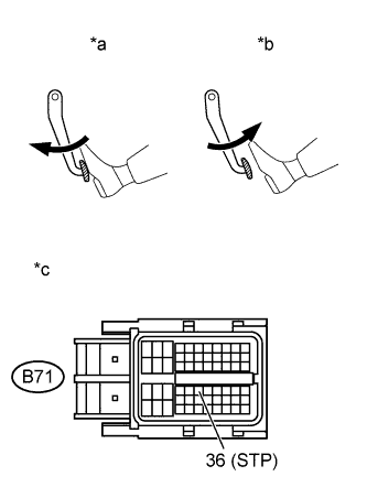
Text in Illustration *a Depressed *b Released *c Front view of wire harness connector
(to ECM)
-
Disconnect the ECM connector.
-
Measure the voltage according to the value(s) in the table below.
Standard Voltage Tester Connection Condition Specified Condition B71-36 (STP) - Body ground Brake pedal is depressed 11 to 14 V Brake pedal is released Below 1.5 V
NG
REPAIR OR REPLACE HARNESS OR CONNECTOR
OK 
REPLACE ECM Click here
-