BRAKE BOOSTER (for TMT Made) INSTALLATION
-
INSTALL BRAKE BOOSTER ASSEMBLY
-
Install a new gasket to the brake booster.
-
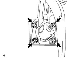
Install the booster with the 4 nuts.
- Torque:
- 14 N*m { 145 kgf*cm, 10 ft.*lbf }
-
Install the push rod clevis.
-
Apply a light coat of lithium soap base glycol grease to the clevis pin.
-
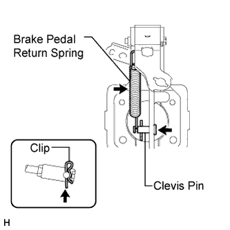
Install the clevis pin and a new clip.
Note
The clip must be installed as shown in the illustration.
-
Install the return spring.
-
Install a new grommet and check valve to the booster.
-
Connect the vacuum hose.
-
Install the vacuum warning switch to the booster and connect the vacuum warning switch connector.
- Torque:
- 14 N*m { 140 kgf*cm, 10 ft.*lbf }
-
-
CHECK AND ADJUST BRAKE BOOSTER PUSH ROD
Tech Tips
Adjust the booster push rod when the master cylinder is replaced with a new one. Adjustment is not necessary when the master cylinder is reinstalled and the booster is replaced with a new one.
-
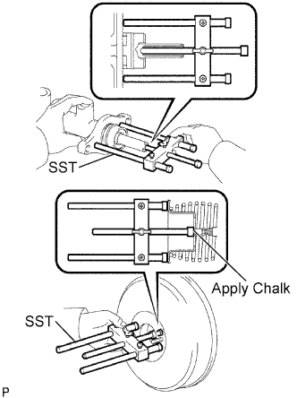
Set SST on the master cylinder and lower the rod of SST until it just touches the piston.
- SST
- 09737-00013
Tech Tips
SST 09737-00012 can also be used.
-
Apply chalk to the flat tip of the rod of SST. Turn SST upside down and measure the clearance between the brake booster push rod and SST.
Standard clearance 0 mm (0 in.) If there is clearance between the main body of SST and the shell of the brake booster, the push rod is protrusion too far. If the chalk does not stick to the tip of the tip of the brake booster push rod, the push rod protrusion is insufficient.
-
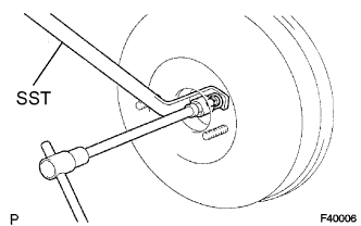
If the clearance is not as specified, adjust the length by holding the rod using SST and turning the tip of the rod using a 7 mm socket driver.
- SST
- 09737-00020
Note
Check the push rod clearance again after adjusting.
-
-
INSTALL BRAKE MASTER CYLINDER SUB-ASSEMBLY (w/ ABS)
-
Install a new O-ring to the master cylinder.
-
Install the master cylinder and bracket (with 3-way) to the booster with the 2 nuts.
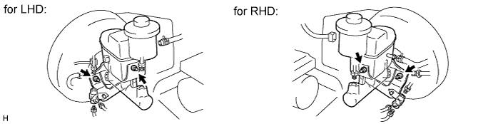
- Torque:
- 13 N*m { 127 kgf*cm, 9 ft.*lbf }
-
Using a union nut wrench, connect the 5 brake lines labeled C to the master cylinder and 3-way.
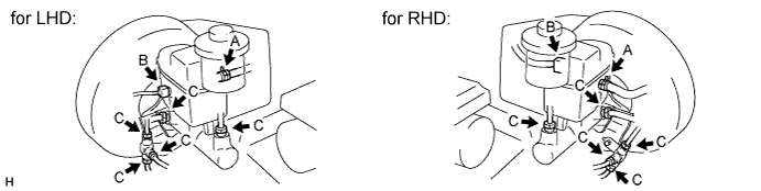
- Torque:
- 15 N*m { 155 kgf*cm, 11 ft.*lbf }
Note
Use the formula to calculate special torque values for situations where a union nut wrench is combined with a torque wrench Click here.
-
Connect the brake fluid level warning switch connector labeled B to the master cylinder.
-
for Manual Transmission:
Connect the clutch reservoir tube labeled A to the master cylinder.
-
-
INSTALL BRAKE MASTER CYLINDER SUB-ASSEMBLY (w/o ABS)
-
Install a new O-ring to the master cylinder.
-
Install the master cylinder and bracket (with 4-way) to the booster with the 2 nuts.
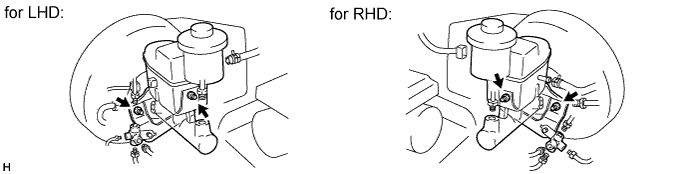
- Torque:
- 13 N*m { 127 kgf*cm, 9 ft.*lbf }
-
Using a union nut wrench, connect the 6 brake lines to the brake master cylinder and 4-way.
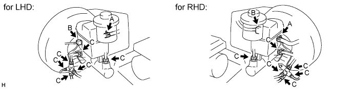
- Torque:
- 15 N*m { 155 kgf*cm, 11 ft.*lbf }
Note
Use the formula to calculate special torque values for situations where a union nut wrench is combined with a torque wrench Click here.
-
Connect the brake fluid level warning switch connector to the master cylinder.
-
Connect the clutch reservoir tube to the master cylinder.
-
-
FILL RESERVOIR WITH BRAKE FLUID
Fluid SAE J1703 or FMVSS No. 116 DOT 3 -
BLEED AIR FROM BRAKE MASTER CYLINDER
Tech Tips
If the master cylinder has been disassembled or if the reservoir becomes empty, bleed air from the master cylinder.
-
Using a union nut wrench, disconnect the 2 brake lines from the master cylinder.
-
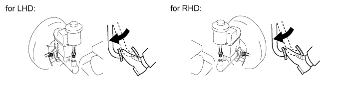
Slowly depress and hold the brake pedal.
-
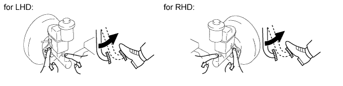
Cover the outer holes with your finger, and release the pedal.
-
Repeat the 2 previous steps 3 or 4 times.
-
Using a union nut wrench, connect the 2 brake lines to the master cylinder.
- Torque:
- 15 N*m { 155 kgf*cm, 11 ft.*lbf }
Note
Use the formula to calculate special torque values for situations where a union nut wrench is combined with a torque wrench Click here.
-
-
BLEED AIR FROM BRAKE LINE
-
Remove the bleeder plug cap.
-
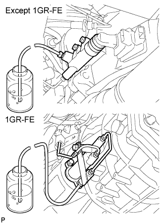
Connect the vinyl tube to the bleeder plugs.
-
Depress the pedal several times, and then loosen the bleeder plug with the pedal depressed.
-
When fluid stops coming out, immediately tighten the bleeder plug. Then release the pedal.
-
Repeat the 2 previous steps until all the air in the brake fluid is gone.
-
Tighten the bleeder plug.
- Torque:
- for front brake
- 11 N*m { 110 kgf*cm, 8 ft.*lbf }
- for rear brake (2WD)
- 11 N*m { 112 kgf*cm, 8 ft.*lbf }
- for rear brake (4WD and Pre-Runner)
- 10 N*m { 102 kgf*cm, 7 ft.*lbf }
-
Install the cap.
-
Bleed air from the brake line for each wheel by repeating the above procedures.
-
-
BLEED AIR FROM CLUTCH LINE (for Manual Transmission)
-
Remove the bleeder plug cap.
-
Connect the vinyl tube to the bleeder plug.
-
Depress the clutch pedal several times, and then loosen the bleeder plug with the pedal depressed.
-
At the point when fluid stops coming out, tighten the bleeder plug, and then release the clutch pedal.
-
Repeat the previous 2 steps until all the air in the fluid is completely bled out.
-
Tighten the bleeder plug.
- Torque:
- 11 N*m { 112 kgf*cm, 8 ft.*lbf }
-
Install the bleeder plug cap.
-
Check that all the air has been bled out of the clutch line.
-
-
CHECK AND ADJUST BRAKE PEDAL HEIGHT
-
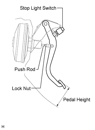
Check the pedal height.
Pedal height from dash panel Model Specified Condition LHD (M/T) 152.9 to 162.9 mm (6.020 to 6.413 in.) LHD (A/T) 154.1 to 164.1 mm (6.067 to 6.461 in.) RHD (M/T) 156.9 to 166.9 mm (6.177 to 6.571 in.) RHD (A/T) 158.1 to 168.1 mm (6.224 to 6.618 in.) -
Adjust the pedal height.
-
Disconnect the connector from the stop light switch.
-
Remove the switch.
-
Loosen the push rod clevis lock nut.
-
Adjust the pedal height by turning the push rod.
-
Tighten the lock nut.
- Torque:
- 26 N*m { 265 kgf*cm, 19 ft.*lbf }
-
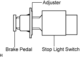
Insert the switch into the adjuster until it slightly touches the pedal.
Note
Do not depress the pedal.
-
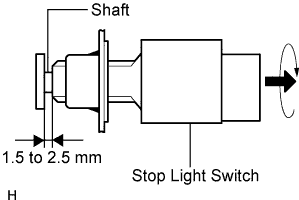
Turn the switch a quarter turn clockwise.
- Torque:
- 1.5 N*m { 15 kgf*cm, 13 in.*lbf, or less }
Note
Do not depress the pedal.
-
Connect the connector to the switch.
-
Check the switch clearance.
Stop light switch clearance 1.5 to 2.5 mm (0.0591 to 0.0984 in.)
-
-
-
CHECK BRAKE PEDAL FREE PLAY
-
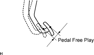
Stop the engine. Depress the pedal several times until there is no vacuum in the booster. Then release the pedal.
-
Depress the pedal until resistance is felt.
-
Check the pedal's free play by measuring the distance between the position in the previous step and the pedal's released position.
Pedal free play 1.0 to 6.0 mm (0.0394 to 0.236 in.) If the free play is not as specified, check the switch clearance in the next step.
If the free play is as specified, proceed to the "check brake pedal reserve distance" procedure.
-
Check the switch clearance.
Stop light switch clearance 1.5 to 2.5 mm (0.0591 to 0.0984 in.) If the clearance is not as specified, adjust the clearance and recheck the pedal's free play.
If the clearance is as specified, troubleshoot the brake system and proceed to the "check brake pedal reserve distance" procedure.
-
-
CHECK BRAKE PEDAL RESERVE DISTANCE
-
Release the parking brake lever. Start the engine.
-
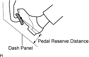
Depress the pedal and check the pedal reserve distance.
-
Depress the pedal with a force of 490 N (50 kgf, 110 lbf).
-
Measure the distance between the pedal and dash panel shown in the illustration.
Pedal reserve distance Model Specified Condition LHD (2WD) 78.0 mm (3.071 in.) LHD (4WD) 85.0 mm (3.347 in.) RHD (2WD) 82.0 mm (3.228 in.) RHD (4WD and pre-runner) 89.0 mm (3.504 in.) If the distance is not as specified, troubleshoot the brake system.
-
-
-
CHECK BRAKE FLUID LEVEL IN RESERVOIR
-
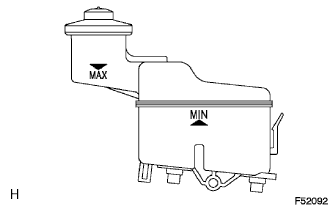
Check the fluid level.
If the brake fluid level is lower that the MIN line, check for leaks and inspect the disc brake pads. If necessary, refill the reservoir with brake fluid to the MAX line after repair or replacement.
Fluid SAE J1703 or FMVSS No. 116 DOT 3
-
-
CHECK FOR BRAKE FLUID LEAKAGE