POP UP HOOD SENSOR REMOVAL

CAUTION / NOTICE / HINT
The necessary procedures (adjustment, calibration, initialization or registration) that must be performed after parts are removed, installed or replaced during the pedestrian detection chamber assembly removal/installation are shown below.
| Replacement Part or Procedure | Necessary Procedures | Effects / Inoperative when not Performed | Link |
|---|---|---|---|
| Disconnect cable from negative (-) battery terminal | Drive the vehicle until stop and start control is permitted (approximately 5 to 60 minutes) | Stop and start system | |
| Memorize steering angle neutral point | LKA/LDA system | ||
| Parking support brake system* | |||
| Pre-collision system | |||
| Adaptive high beam system | |||
Lighting system (EXT) |
|||
| Variable gear ratio steering system | |||
| Parking assist monitor system | |||
| Panoramic View Monitor System | |||
| Initialize Rear Door Sunshade System | Rear door sunshade system | ||
| Initialize power trunk lid system | Power trunk lid system | ||
| Front bumper assembly (Including removal and installation) |
w/ Parking Support Brake System: |
Parking support brake system | |
| Front television camera view adjustment | Panoramic view monitor system |
Click here Click here
PROCEDURE
-
PRECAUTION
Note
After turning the engine switch off, waiting time may be required before disconnecting the cable from the negative (-) battery terminal. Therefore, make sure to read the disconnecting the cable from the negative (-) battery terminal notices before proceeding with work.
-
REMOVE LUGGAGE COMPARTMENT MAT SUB-ASSEMBLY
-
DISCONNECT CABLE FROM NEGATIVE BATTERY TERMINAL
CAUTION:
-
Wait at least 90 seconds after disconnecting the cable from the negative (-) battery terminal to disable the SRS system.
-
If the airbag deploys for any reason, it may cause a serious accident.
Note
When disconnecting the cable, some systems need to be initialized after the cable is reconnected.
-
-
REMOVE FRONT BUMPER ASSEMBLY
except Sports Package:
for Sports Package:
-
REMOVE FRONT BUMPER ENERGY ABSORBER SUB-ASSEMBLY
except Sports Package:
for Sports Package:
-
REMOVE PEDESTRIAN DETECTION CHAMBER ASSEMBLY
Note
When inspect the pedestrian detection chamber assembly, do not remove the pedestrian protection sensor.
-
The installation bolt and nut for the pedestrian protection sensor is a non-reusable part.
-
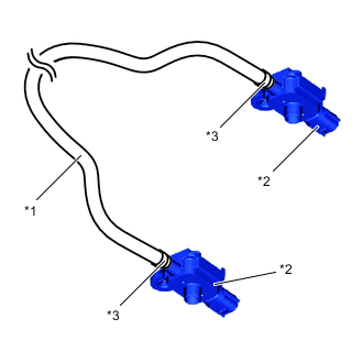
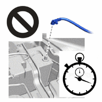
*1 Pedestrian Detection Chamber *2 Pedestrian Protection Sensor *3 Clip To preserve the airtight seal of the pedestrian detection chamber.
-
Do not open/close or move the tightening clips of the pedestrian detection chamber and pedestrian protection sensor.
-
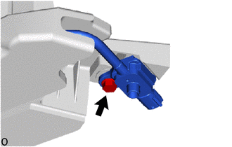
Remove the bolt and pedestrian protection sensor from the front energy absorber mounting reinforcement RH.
Note
-
When inspect the pedestrian detection chamber assembly, do not remove the pedestrian protection sensor.
-
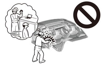
Do not subject the pedestrian detection chamber assembly to any strong impact (such as dropping).
-
If the pedestrian protection sensor is subjected to any strong impact, replace the pedestrian detection chamber assembly with a new one.
-
Hold the pedestrian protection sensor so as not to damage the front energy absorber mounting reinforcement RH.
-
Do not pull only pedestrian protection sensor.
-
Do not pull only pedestrian detection chamber.
-
Do not reuse the bolt.
Tech Tips
Use the same procedure for the opposite side.
-
-
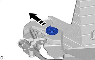

Remove in this Direction Remove the nut.
Note
Do not reuse the nut.
Tech Tips
Use the same procedure for the opposite side.
-
Using a clip remover, remove the 2 clips from the RH side of the front bumper energy absorber.
Tech Tips
Tape the clip remover tip before use.
-
Detach the hook and remove the front energy absorber mounting reinforcement RH from the RH side of the front bumper energy absorber.
-
Using a clip remover, remove the 2 clips from the LH side of the front bumper energy absorber.
Tech Tips
Tape the clip remover tip before use.
-
Detach the hook and remove the front energy absorber mounting reinforcement LH from the LH side of the front bumper energy absorber.
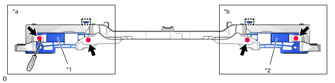
*1 Front Energy Absorber Mounting Reinforcement RH *2 Front Energy Absorber Mounting Reinforcement LH *a Front Bumper Energy Absorber RH Side *b Front Bumper Energy Absorber LH Side 
Protective Tape - - -
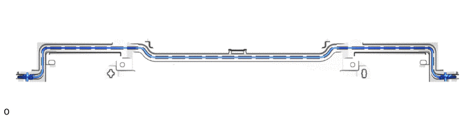
Remove the pedestrian detection chamber from the pedestrian detection chamber connection area of the front bumper energy absorber.
Note
-
Do not pull only pedestrian protection sensor.
-
Do not pull only pedestrian detection chamber.
-
Do not damage the pedestrian detection chamber connection area of the front bumper energy absorber.
-
If a pedestrian detection chamber connection area is damaged, replace the front bumper energy absorber with a new one.
-
-