METER / GAUGE SYSTEM, Diagnostic DTC:B1507, B1508
| DTC Code | DTC Name |
|---|---|
| B1507 | Open in Turn Signal Circuit |
| B1508 | Short in Turn Signal / Hazard Flasher Circuit |
DESCRIPTION
These DTCs are stored when the combination meter assembly detects an open in a turn signal light circuit, or a short in a turn signal light circuit or the hazard warning light circuit.
| DTC No. | Detection Item | DTC Detection Condition | Trouble Area | Memory | Note |
|---|---|---|---|---|---|
| B1507 | Open in Turn Signal Circuit | When IG voltage is 9.5 V or more and the following condition is detected:
|
|
DTC stored | - |
| B1508 | Short in Turn Signal / Hazard Flasher Circuit | When IG voltage is 9.5 V or more and the following condition is detected:
|
|
DTC stored | - |
-
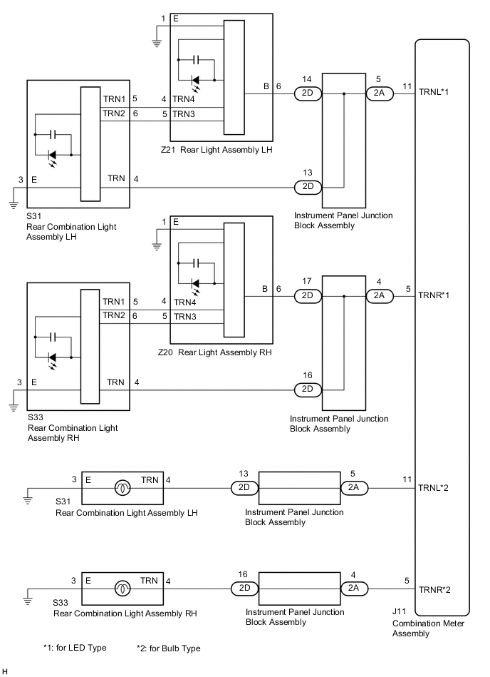
*1: for LED Type
-
*2: for Bulb Type
WIRING DIAGRAM
-
for Front and Side Turn Signal Light
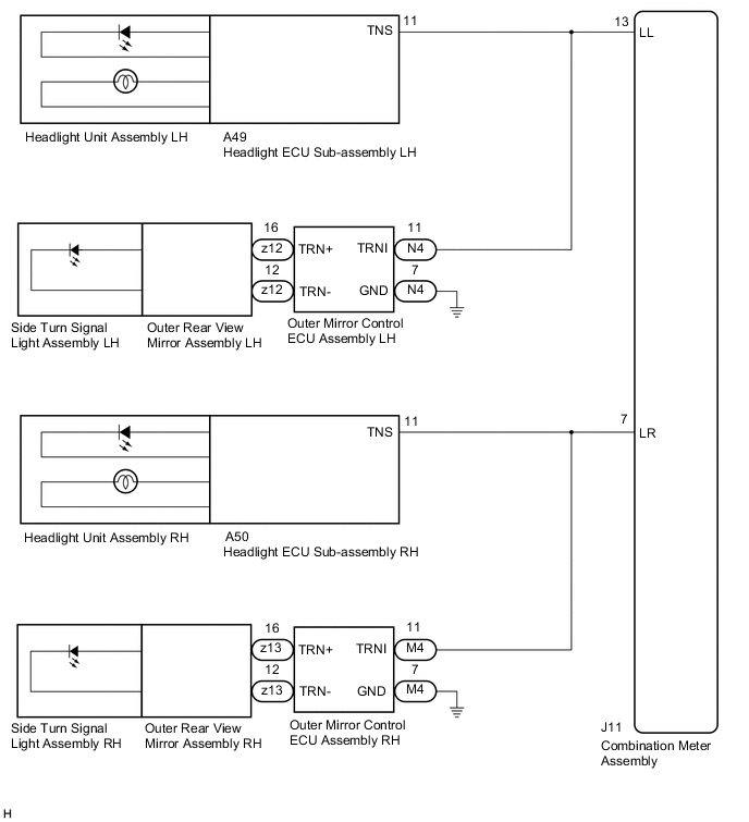
-
for Rear Turn Signal Light
CAUTION / NOTICE / HINT
Note
Inspect the LEDs and bulbs for this system before performing the following procedure.
PROCEDURE
-
INSPECT LIGHTS
-
Inspect the illumination of each turn signal light.
Result Result Proceed to Front or side turn signal light does not blink or flash at the correct speed. A Rear turn signal light does not blink or flash at the correct speed. B
B 
CONFIRM MODEL Click here
A 
-
-
INSPECT LIGHTS
-
Inspect the illumination of each turn signal light.
Result Result Proceed to All RH turn signal lights or all LH turn signal lights do not blink or flash at the correct speed. A RH side turn signal light does not blink or flash at the correct speed. B LH side turn signal light does not blink or flash at the correct speed. C
B
CHECK TURN SIGNAL LIGHTS (RH SIDE) Click here
C
CHECK TURN SIGNAL LIGHTS (LH SIDE) Click here
A
-
-
CHECK HARNESS AND CONNECTOR (COMBINATION METER ASSEMBLY - INSTRUMENT PANEL JUNCTION BLOCK ASSEMBLY OR BODY GROUND)
-
for RH side:
-
Disconnect the J11 combination meter assembly connector.
-
Disconnect the A50 headlight ECU sub-assembly RH connector.
-
Disconnect the M4 outer mirror control ECU assembly RH connector.
-
Measure the resistance according to the value(s) in the table below.
Standard Resistance (Check for Open) Tester Connection Condition Specified Condition J11-7 (LR) - A50-11 (TNS) or M4-11 (TRNI) Always Below 1 Ω Standard Resistance (Check for Short) Tester Connection Condition Specified Condition J11-7 (LR), A50-11 (TNS) or M4-11 (TRNI) - Body ground Always 10 kΩ or higher
-
-
for LH side:
-
Disconnect the J11 combination meter assembly connector.
-
Disconnect the A49 headlight ECU sub-assembly LH connector.
-
Disconnect the N4 outer mirror control ECU assembly LH connector.
-
Measure the resistance according to the value(s) in the table below.
Standard Resistance (Check for Open) Tester Connection Condition Specified Condition J11-13 (LL) - A49-11 (TNS) or N4-11 (TRNI) Always Below 1 Ω Standard Resistance (Check for Short) Tester Connection Condition Specified Condition J11-13 (LL), A49-11 (TNS) or N4-11 (TRNI) - Body ground Always 10 kΩ or higher
Result Proceed to OK NG -
OK 
REPLACE COMBINATION METER ASSEMBLY Click here
NG
REPAIR OR REPLACE HARNESS OR CONNECTOR
-
-
CHECK TURN SIGNAL LIGHTS (RH SIDE)
-
Turn the engine switch on (IG).
-
Set the headlight dimmer switch assembly to the right turn switch position.
-
Check the operation of the turn signal lights (RH side).
Result Result Proceed to Front turn signal light RH does not blink or flash at the correct speed. A Side turn signal light RH does not blink or flash at the correct speed. B
B
CHECK HARNESS AND CONNECTOR (OUTER MIRROR CONTROL ECU ASSEMBLY RH - COMBINATION METER ASSEMBLY OR BODY GROUND) Click here
A
-
-
CHECK HARNESS AND CONNECTOR (HEADLIGHT ECU SUB-ASSEMBLY RH - COMBINATION METER ASSEMBLY OR BODY GROUND)
-
Disconnect the J11 combination meter assembly connector.
-
Disconnect the A50 headlight ECU sub-assembly RH connector.
-
Disconnect the M4 outer mirror control ECU assembly RH connector.
-
Measure the resistance according to the value(s) in the table below.
Standard Resistance (Check for Open) Tester Connection Condition Specified Condition J11-7 (LR) - A50-11 (TNS) Always Below 1 Ω Standard Resistance (Check for Short) Tester Connection Condition Specified Condition J11-7 (LR) or A50-11 (TNS) - Body ground Always 10 kΩ or higher Result Proceed to OK NG
NG
REPAIR OR REPLACE HARNESS OR CONNECTOR
OK
-
-
REPLACE HEADLIGHT ECU SUB-ASSEMBLY RH
-
Replace the headlight ECU sub-assembly RH with a new or known good one.
-
Check for DTCs.
Body Electrical > Combination Meter > Trouble CodesResult Result Proceed to DTCs are output. A DTCs are not output. B
A
REPLACE HEADLIGHT UNIT ASSEMBLY RH for Triple Beam Headlight: Click here
REPLACE HEADLIGHT UNIT ASSEMBLY RH for Single Beam Headlight: Click hereB
END
-
-
CHECK HARNESS AND CONNECTOR (OUTER MIRROR CONTROL ECU ASSEMBLY RH - COMBINATION METER ASSEMBLY OR BODY GROUND)
-
Disconnect the J11 combination meter assembly connector.
-
Disconnect the A50 headlight ECU sub-assembly RH connector.
-
Disconnect the M4 outer mirror control ECU assembly RH connector.
-
Measure the resistance according to the value(s) in the table below.
Standard Resistance (Check for Open) Tester Connection Condition Specified Condition J11-7 (LR) - M4-11 (TRNI) Always Below 1 Ω M4-7 (GND) - Body ground Always Below 1 Ω Standard Resistance (Check for Short) Tester Connection Condition Specified Condition J11-7 (LR) or M4-11 (TRNI) - Body ground Always 10 kΩ or higher Result Proceed to OK NG
NG
REPAIR OR REPLACE HARNESS OR CONNECTOR
OK
-
-
REPLACE OUTER MIRROR CONTROL ECU ASSEMBLY RH
-
Replace the outer mirror control ECU assembly RH with a new or known good one.
-
Check for DTCs.
Body Electrical > Combination Meter > Trouble CodesResult Result Proceed to DTCs are output. A DTCs are not output. B
A
REPLACE SIDE TURN SIGNAL LIGHT ASSEMBLY RH Click here
B
END
-
-
CHECK TURN SIGNAL LIGHTS (LH SIDE)
-
Turn the engine switch on (IG).
-
Set the headlight dimmer switch assembly to the left turn switch position.
-
Check the operation of the turn signal lights (LH side).
Result Result Proceed to Front turn signal light LH does not blink or flash at the correct speed. A Side turn signal light LH does not blink or flash at the correct speed. B
B
CHECK HARNESS AND CONNECTOR (OUTER MIRROR CONTROL ECU ASSEMBLY LH - COMBINATION METER ASSEMBLY OR BODY GROUND) Click here
A
-
-
CHECK HARNESS AND CONNECTOR (HEADLIGHT ECU SUB-ASSEMBLY LH - COMBINATION METER ASSEMBLY OR BODY GROUND)
-
Disconnect the J11 combination meter assembly connector.
-
Disconnect the A49 headlight ECU sub-assembly LH connector.
-
Disconnect the N4 outer mirror control ECU assembly LH connector.
-
Measure the resistance according to the value(s) in the table below.
Standard Resistance (Check for Open) Tester Connection Condition Specified Condition J11-13 (LL) - A49-11 (TNS) Always Below 1 Ω Standard Resistance (Check for Short) Tester Connection Condition Specified Condition J11-13 (LL) or A49-11 (TNS) - Body ground Always 10 kΩ or higher Result Proceed to OK NG
NG
REPAIR OR REPLACE HARNESS OR CONNECTOR
OK
-
-
REPLACE HEADLIGHT ECU SUB-ASSEMBLY LH
-
Replace the headlight ECU sub-assembly LH with a new or known good one.
-
Check for DTCs.
Body Electrical > Combination Meter > Trouble CodesResult Result Proceed to DTCs are output. A DTCs are not output. B
A
REPLACE HEADLIGHT UNIT ASSEMBLY LH for Triple Beam Headlight: Click here
REPLACE HEADLIGHT UNIT ASSEMBLY LH for Single Beam Headlight: Click hereB
END
-
-
CHECK HARNESS AND CONNECTOR (OUTER MIRROR CONTROL ECU ASSEMBLY LH - COMBINATION METER ASSEMBLY OR BODY GROUND)
-
Disconnect the J11 combination meter assembly connector.
-
Disconnect the A49 headlight ECU sub-assembly LH connector.
-
Disconnect the N4 outer mirror control ECU assembly LH connector.
-
Measure the resistance according to the value(s) in the table below.
Standard Resistance (Check for Open) Tester Connection Condition Specified Condition J11-13 (LL) - N4-11 (TRNI) Always Below 1 Ω Standard Resistance (Check for Short) Tester Connection Condition Specified Condition J11-13 (LL) or N4-11 (TRNI) - Body ground Always 10 kΩ or higher Result Proceed to OK NG
NG
REPAIR OR REPLACE HARNESS OR CONNECTOR
OK
-
-
REPLACE OUTER MIRROR CONTROL ECU ASSEMBLY LH
-
Replace the outer mirror control ECU assembly LH with a new or known good one.
-
Check for DTCs.
Body Electrical > Combination Meter > Trouble CodesResult Result Proceed to DTCs are output. A DTCs are not output. B
A
REPLACE SIDE TURN SIGNAL LIGHT ASSEMBLY LH Click here
B
END
-
-
CONFIRM MODEL
-
Choose the rear turn signal light type to be inspected.
Result Result Proceed to for LED Type A for Bulb Type B
B
INSPECT LIGHTS Click here
A
-
-
INSPECT LIGHTS
-
Inspect the illumination of each turn signal light.
Result Result Proceed to RH side turn signal light does not blink. A RH side turn signal light does not flash at the correct speed. B LH side turn signal light does not blink. C LH side turn signal light does not flash at the correct speed. D
B
CHECK HARNESS AND CONNECTOR (COMBINATION METER ASSEMBLY OR INSTRUMENT PANEL JUNCTION BLOCK ASSEMBLY - BODY GROUND) Click here
C
CHECK HARNESS AND CONNECTOR (COMBINATION METER ASSEMBLY - INSTRUMENT PANEL JUNCTION BLOCK ASSEMBLY OR BODY GROUND) Click here
D
CHECK HARNESS AND CONNECTOR (COMBINATION METER ASSEMBLY OR INSTRUMENT PANEL JUNCTION BLOCK ASSEMBLY - BODY GROUND) Click here
A
-
-
CHECK HARNESS AND CONNECTOR (COMBINATION METER ASSEMBLY - INSTRUMENT PANEL JUNCTION BLOCK ASSEMBLY OR BODY GROUND)
-
Disconnect the J11 combination meter assembly connector.
-
Disconnect the 2A instrument panel junction block assembly connector.
-
Measure the resistance according to the value(s) in the table below.
Standard Resistance Tester Connection Condition Specified Condition J11-5 (TRNR) - 2A-4 Always Below 1 Ω Result Proceed to OK NG
NG
REPAIR OR REPLACE HARNESS OR CONNECTOR
OK
-
-
INSPECT INSTRUMENT PANEL JUNCTION BLOCK ASSEMBLY
-
Remove the instrument panel junction block assembly.
-
Measure the resistance according to the value(s) in the table below.

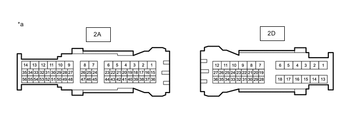
*a Component without harness connected (Instrument Panel Junction Block Assembly) - - Standard Resistance Tester Connection Condition Specified Condition 2A-4 - 2D-17 Always Below 1 Ω 2A-4 - 2D-16 Always Below 1 Ω Result Proceed to OK NG
NG
REPLACE INSTRUMENT PANEL JUNCTION BLOCK ASSEMBLY Click here
OK
-
-
CHECK HARNESS AND CONNECTOR (INSTRUMENT PANEL JUNCTION BLOCK ASSEMBLY - REAR LIGHT ASSEMBLY RH)
-
Disconnect the Z20 rear light assembly RH connector.
-
Measure the resistance according to the value(s) in the table below.
Standard Resistance Tester Connection Condition Specified Condition Z20-6 (B) - 2D-17 Always Below 1 Ω Z20-1 (E) - Body ground Always Below 1 Ω Result Proceed to OK NG
NG
REPAIR OR REPLACE HARNESS OR CONNECTOR
OK
-
-
CHECK HARNESS AND CONNECTOR (REAR LIGHT ASSEMBLY RH - REAR COMBINATION LIGHT ASSEMBLY RH)
-
Disconnect the S33 rear combination light assembly RH connector.
-
Measure the resistance according to the value(s) in the table below.
Standard Resistance Tester Connection Condition Specified Condition Z20-4 (TRN4) - S33-5 (TRN1) Always Below 1 Ω Z20-5 (TRN3) - S33-6 (TRN2) Always Below 1 Ω Result Proceed to OK NG
NG
REPAIR OR REPLACE HARNESS OR CONNECTOR
OK
-
-
CHECK HARNESS AND CONNECTOR (INSTRUMENT PANEL JUNCTION BLOCK ASSEMBLY - REAR COMBINATION LIGHT ASSEMBLY RH)
-
Measure the resistance according to the value(s) in the table below.
Standard Resistance Tester Connection Condition Specified Condition 2D-16 - S33-4 (TRN) Always Below 1 Ω Result Proceed to OK NG
NG
REPAIR OR REPLACE HARNESS OR CONNECTOR
OK
-
-
REPLACE REAR LIGHT ASSEMBLY RH
-
Replace the rear light assembly RH with a new or known good one.
-
Check for DTCs.
Body Electrical > Combination Meter > Trouble CodesResult Result Proceed to DTCs are output. A DTCs are not output. B
B
END
A
-
-
REPLACE REAR COMBINATION LIGHT ASSEMBLY RH
-
Replace the rear combination light assembly RH with a new or known good one.
-
Check for DTCs.
Body Electrical > Combination Meter > Trouble CodesResult Result Proceed to DTCs are output. A DTCs are not output. B
A
REPLACE COMBINATION METER ASSEMBLY Click here
B
END
-
-
CHECK HARNESS AND CONNECTOR (COMBINATION METER ASSEMBLY OR INSTRUMENT PANEL JUNCTION BLOCK ASSEMBLY - BODY GROUND)
-
Disconnect the J11 combination meter assembly connector.
-
Disconnect the 2A instrument panel junction block assembly connector.
-
Measure the resistance according to the value(s) in the table below.
Standard Resistance Tester Connection Condition Specified Condition J11-5 (TRNR) or 2A-4 - Body ground Always 10 kΩ or higher Result Proceed to OK NG
NG
REPAIR OR REPLACE HARNESS OR CONNECTOR
OK
-
-
INSPECT INSTRUMENT PANEL JUNCTION BLOCK ASSEMBLY
-
Remove the instrument panel junction block assembly.
-
Measure the resistance according to the value(s) in the table below.

*a Component without harness connected
(Instrument Panel Junction Block Assembly)
- - Standard Resistance Tester Connection Condition Specified Condition 2A-4, 2D-17 or 2D-16 - Body ground Always 10 kΩ or higher Result Proceed to OK NG
NG
REPLACE INSTRUMENT PANEL JUNCTION BLOCK ASSEMBLY Click here
OK
-
-
CHECK HARNESS AND CONNECTOR (INSTRUMENT PANEL JUNCTION BLOCK ASSEMBLY OR REAR LIGHT ASSEMBLY RH - BODY GROUND)
-
Disconnect the Z20 rear light assembly RH connector.
-
Measure the resistance according to the value(s) in the table below.
Standard Resistance Tester Connection Condition Specified Condition 2D-17 or Z20-6 (B) - Body ground Always 10 kΩ or higher Result Proceed to OK NG
NG
REPAIR OR REPLACE HARNESS OR CONNECTOR
OK
-
-
CHECK HARNESS AND CONNECTOR (REAR LIGHT ASSEMBLY RH OR REAR COMBINATION LIGHT ASSEMBLY RH - BODY GROUND)
-
Disconnect the S33 rear combination light assembly RH connector.
-
Measure the resistance according to the value(s) in the table below.
Standard Resistance Tester Connection Condition Specified Condition Z20-4 (TRN4) or S33-5 (TRN1) - Body ground Always 10 kΩ or higher Z20-5 (TRN3) or S33-6 (TRN2) - Body ground Always 10 kΩ or higher Result Proceed to OK NG
NG
REPAIR OR REPLACE HARNESS OR CONNECTOR
OK
-
-
CHECK HARNESS AND CONNECTOR (INSTRUMENT PANEL JUNCTION BLOCK ASSEMBLY OR REAR COMBINATION LIGHT ASSEMBLY RH - BODY GROUND)
-
Measure the resistance according to the value(s) in the table below.
Standard Resistance Tester Connection Condition Specified Condition 2D-16 or S33-4 (TRN) - Body ground Always 10 kΩ or higher Result Proceed to OK NG
NG
REPAIR OR REPLACE HARNESS OR CONNECTOR
OK
-
-
REPLACE REAR LIGHT ASSEMBLY RH
-
Replace the rear light assembly RH with a new or known good one.
-
Check for DTCs.
Body Electrical > Combination Meter > Trouble CodesResult Result Proceed to DTCs are output. A DTCs are not output. B
B
END
A
-
-
REPLACE REAR COMBINATION LIGHT ASSEMBLY RH
-
Replace the rear combination light assembly RH with a new or known good one.
-
Check for DTCs.
Body Electrical > Combination Meter > Trouble CodesResult Result Proceed to DTCs are output. A DTCs are not output. B
A
REPLACE COMBINATION METER ASSEMBLY Click here
B
END
-
-
CHECK HARNESS AND CONNECTOR (COMBINATION METER ASSEMBLY - INSTRUMENT PANEL JUNCTION BLOCK ASSEMBLY OR BODY GROUND)
-
Disconnect the J11 combination meter assembly connector.
-
Disconnect the 2A instrument panel junction block assembly connector.
-
Measure the resistance according to the value(s) in the table below.
Standard Resistance Tester Connection Condition Specified Condition J11-11 (TRNL) - 2A-5 Always Below 1 Ω Result Proceed to OK NG
NG
REPAIR OR REPLACE HARNESS OR CONNECTOR
OK
-
-
INSPECT INSTRUMENT PANEL JUNCTION BLOCK ASSEMBLY
-
Remove the instrument panel junction block assembly.
-
Measure the resistance according to the value(s) in the table below.

*a Component without harness connected
(Instrument Panel Junction Block Assembly)
- - Standard Resistance Tester Connection Condition Specified Condition 2A-5 - 2D-14 Always Below 1 Ω 2A-5 - 2D-13 Always Below 1 Ω Result Proceed to OK NG
NG
REPLACE INSTRUMENT PANEL JUNCTION BLOCK ASSEMBLY Click here
OK
-
-
CHECK HARNESS AND CONNECTOR (INSTRUMENT PANEL JUNCTION BLOCK ASSEMBLY - REAR LIGHT ASSEMBLY LH)
-
Disconnect the Z21 rear light assembly LH connector.
-
Disconnect the 2D instrument panel junction block assembly connector.
-
Measure the resistance according to the value(s) in the table below.
Standard Resistance Tester Connection Condition Specified Condition Z21-6 (B) - 2D-14 Always Below 1 Ω Z21-1 (E) - Body ground Always Below 1 Ω Result Proceed to OK NG
NG
REPAIR OR REPLACE HARNESS OR CONNECTOR
OK
-
-
CHECK HARNESS AND CONNECTOR (REAR LIGHT ASSEMBLY LH - REAR COMBINATION LIGHT ASSEMBLY LH)
-
Disconnect the S31 rear combination light assembly LH connector.
-
Measure the resistance according to the value(s) in the table below.
Standard Resistance Tester Connection Condition Specified Condition Z21-4 (TRN4) - S31-5 (TRN1) Always Below 1 Ω Z21-5 (TRN3) - S31-6 (TRN2) Always Below 1 Ω Result Proceed to OK NG
NG
REPAIR OR REPLACE HARNESS OR CONNECTOR
OK
-
-
CHECK HARNESS AND CONNECTOR (INSTRUMENT PANEL JUNCTION BLOCK ASSEMBLY - REAR COMBINATION LIGHT ASSEMBLY LH)
-
Measure the resistance according to the value(s) in the table below.
Standard Resistance Tester Connection Condition Specified Condition 2D-13 - S31-4 (TRN) Always Below 1 Ω Result Proceed to OK NG
NG
REPAIR OR REPLACE HARNESS OR CONNECTOR
OK
-
-
REPLACE REAR LIGHT ASSEMBLY LH
-
Replace the rear light assembly LH with a new or known good one.
-
Check for DTCs.
Body Electrical > Combination Meter > Trouble CodesResult Result Proceed to DTCs are output. A DTCs are not output. B
B
END
A
-
-
REPLACE REAR COMBINATION LIGHT ASSEMBLY LH
-
Replace the rear combination light assembly LH with a new or known good one.
-
Check for DTCs.
Body Electrical > Combination Meter > Trouble CodesResult Result Proceed to DTCs are output. A DTCs are not output. B
A
REPLACE COMBINATION METER ASSEMBLY Click here
B
END
-
-
CHECK HARNESS AND CONNECTOR (COMBINATION METER ASSEMBLY OR INSTRUMENT PANEL JUNCTION BLOCK ASSEMBLY - BODY GROUND)
-
Disconnect the J11 combination meter assembly connector.
-
Disconnect the 2A instrument panel junction block assembly connector.
-
Measure the resistance according to the value(s) in the table below.
Standard Resistance Tester Connection Condition Specified Condition J11-11 (TRNL) or 2A-5 - Body ground Always 10 kΩ or higher Result Proceed to OK NG
NG
REPAIR OR REPLACE HARNESS OR CONNECTOR
OK
-
-
INSPECT INSTRUMENT PANEL JUNCTION BLOCK ASSEMBLY
-
Remove the instrument panel junction block assembly.
-
Measure the resistance according to the value(s) in the table below.

*a Component without harness connected
(Instrument Panel Junction Block Assembly)
- - Standard Resistance Tester Connection Condition Specified Condition 2A-5, 2D-14 or 2D-13 - Body ground Always 10 kΩ or higher Result Proceed to OK NG
NG
REPLACE INSTRUMENT PANEL JUNCTION BLOCK ASSEMBLY Click here
OK
-
-
CHECK HARNESS AND CONNECTOR (INSTRUMENT PANEL JUNCTION BLOCK ASSEMBLY OR REAR LIGHT ASSEMBLY LH - BODY GROUND)
-
Disconnect the Z21 rear light assembly LH connector.
-
Measure the resistance according to the value(s) in the table below.
Standard Resistance Tester Connection Condition Specified Condition 2D-14 or Z21-6 (B) - Body ground Always 10 kΩ or higher Result Proceed to OK NG
NG
REPAIR OR REPLACE HARNESS OR CONNECTOR
OK
-
-
CHECK HARNESS AND CONNECTOR (REAR LIGHT ASSEMBLY LH OR REAR COMBINATION LIGHT ASSEMBLY LH - BODY GROUND)
-
Disconnect the S31 rear combination light assembly LH connector.
-
Measure the resistance according to the value(s) in the table below.
Standard Resistance Tester Connection Condition Specified Condition Z21-4 (TRN4) or S31-5 (TRN1) - Body ground Always 10 kΩ or higher Z21-5 (TRN3) or S31-6 (TRN2) - Body ground Always 10 kΩ or higher Result Proceed to OK NG
NG
REPAIR OR REPLACE HARNESS OR CONNECTOR
OK
-
-
CHECK HARNESS AND CONNECTOR (INSTRUMENT PANEL JUNCTION BLOCK ASSEMBLY OR REAR COMBINATION LIGHT ASSEMBLY LH - BODY GROUND)
-
Measure the resistance according to the value(s) in the table below.
Standard Resistance Tester Connection Condition Specified Condition 2D-13 or S31-4 (TRN) - Body ground Always 10 kΩ or higher Result Proceed to OK NG
NG
REPAIR OR REPLACE HARNESS OR CONNECTOR
OK
-
-
REPLACE REAR LIGHT ASSEMBLY LH
-
Replace the rear light assembly LH with a new or known good one.
-
Check for DTCs.
Body Electrical > Combination Meter > Trouble CodesResult Result Proceed to DTCs are output. A DTCs are not output. B
B
END
A
-
-
REPLACE REAR COMBINATION LIGHT ASSEMBLY LH
-
Replace the rear combination light assembly LH with a new or known good one.
-
Check for DTCs.
Body Electrical > Combination Meter > Trouble CodesResult Result Proceed to DTCs are output. A DTCs are not output. B
A
REPLACE COMBINATION METER ASSEMBLY Click here
B
END
-
-
INSPECT LIGHTS
-
Inspect the illumination of each turn signal light.
Result Result Proceed to RH side turn signal light does not blink or flash at the correct speed. A LH side turn signal light does not blink or flash at the correct speed. B
B
CHECK HARNESS AND CONNECTOR (COMBINATION METER ASSEMBLY - INSTRUMENT PANEL JUNCTION BLOCK ASSEMBLY OR BODY GROUND) Click here
A
-
-
CHECK HARNESS AND CONNECTOR (COMBINATION METER ASSEMBLY - INSTRUMENT PANEL JUNCTION BLOCK ASSEMBLY OR BODY GROUND)
-
Disconnect the J11 combination meter assembly connector.
-
Disconnect the 2A instrument panel junction block assembly connector.
-
Measure the resistance according to the value(s) in the table below.
Standard Resistance (Check for Open) Tester Connection Condition Specified Condition J11-5 (TRNR) - 2A-4 Always Below 1 Ω Standard Resistance (Check for Short) Tester Connection Condition Specified Condition J11-5 (TRNR) or 2A-4 - Body ground Always 10 kΩ or higher Result Proceed to OK NG
NG
REPAIR OR REPLACE HARNESS OR CONNECTOR
OK
-
-
INSPECT INSTRUMENT PANEL JUNCTION BLOCK ASSEMBLY
-
Remove the instrument panel junction block assembly.
-
Measure the resistance according to the value(s) in the table below.

*a Component without harness connected
(Instrument Panel Junction Block Assembly)
- - Standard Resistance (Check for Open) Tester Connection Condition Specified Condition 2A-4 - 2D-16 Always Below 1 Ω Standard Resistance (Check for Short) Tester Connection Condition Specified Condition 2A-4 or 2D-16 - Body ground Always 10 kΩ or higher Result Proceed to OK NG
NG
REPLACE INSTRUMENT PANEL JUNCTION BLOCK ASSEMBLY Click here
OK
-
-
CHECK HARNESS AND CONNECTOR (REAR COMBINATION LIGHT ASSEMBLY RH - INSTRUMENT PANEL JUNCTION BLOCK ASSEMBLY OR BODY GROUND)
-
Disconnect the S33 rear combination light assembly RH connector.
-
Measure the resistance according to the value(s) in the table below.
Standard Resistance (Check for Open) Tester Connection Condition Specified Condition S33-4 (TRN) - 2D-16 Always Below 1 Ω S33-3 (E) - Body ground Always Below 1 Ω Standard Resistance (Check for Short) Tester Connection Condition Specified Condition S33-4 (TRN) or 2D-16 - Body ground Always 10 kΩ or higher Result Proceed to OK NG
OK
REPLACE REAR COMBINATION LIGHT ASSEMBLY RH Click here
NG
REPAIR OR REPLACE HARNESS OR CONNECTOR
-
-
CHECK HARNESS AND CONNECTOR (COMBINATION METER ASSEMBLY - INSTRUMENT PANEL JUNCTION BLOCK ASSEMBLY OR BODY GROUND)
-
Disconnect the J11 combination meter assembly connector.
-
Disconnect the 2A instrument panel junction block assembly connector.
-
Measure the resistance according to the value(s) in the table below.
Standard Resistance (Check for Open) Tester Connection Condition Specified Condition J11-11 (TRNL) - 2A-5 Always Below 1 Ω Standard Resistance (Check for Short) Tester Connection Condition Specified Condition J11-11 (TRNL) or 2A-5 - Body ground Always 10 kΩ or higher Result Proceed to OK NG
NG
REPAIR OR REPLACE HARNESS OR CONNECTOR
OK
-
-
INSPECT INSTRUMENT PANEL JUNCTION BLOCK ASSEMBLY
-
Remove the instrument panel junction block assembly.
-
Measure the resistance according to the value(s) in the table below.
*a Component without harness connected
(Instrument Panel Junction Block Assembly)
- - Standard Resistance (Check for Open) Tester Connection Condition Specified Condition 2A-5 - 2D-13 Always Below 1 Ω Standard Resistance (Check for Short) Tester Connection Condition Specified Condition 2A-5 or 2D-13 - Body ground Always 10 kΩ or higher Result Proceed to OK NG
NG
REPLACE INSTRUMENT PANEL JUNCTION BLOCK ASSEMBLY Click here
OK
-
-
CHECK HARNESS AND CONNECTOR (REAR COMBINATION LIGHT ASSEMBLY LH - INSTRUMENT PANEL JUNCTION BLOCK ASSEMBLY OR BODY GROUND)
-
Disconnect the S31 rear combination light assembly LH connector.
-
Measure the resistance according to the value(s) in the table below.
Standard Resistance (Check for Open) Tester Connection Condition Specified Condition S31-4 (TRN) - 2D-13 Always Below 1 Ω S31-3 (E) - Body ground Always Below 1 Ω Standard Resistance (Check for Short) Tester Connection Condition Specified Condition S31-4 (TRN) or 2D-13 - Body ground Always 10 kΩ or higher Result Proceed to OK NG
OK
REPLACE REAR COMBINATION LIGHT ASSEMBLY LH Click here
NG
REPAIR OR REPLACE HARNESS OR CONNECTOR
-