VEHICLE STABILITY CONTROL SYSTEM, Diagnostic DTC:C1282
| DTC Code | DTC Name |
|---|---|
| C1282 | Center Differential Lock Position Switch |
DESCRIPTION
DTC C1282 is stored only in Test Mode.
| DTC Code | DTC Detection Condition | Trouble area |
|---|---|---|
| C1282 | Stored during Test Mode. |
|
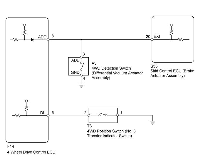
WIRING DIAGRAM
INSPECTION PROCEDURE
Note
-
After replacing the brake actuator assembly, perform calibration Click here.
-
Before disconnecting the connector, make sure that there are no problems with the connection.
-
After disconnecting the connector, make sure that the connector case and terminals are not deformed or corroded.
PROCEDURE
-
CHECK TERMINAL VOLTAGE (EXI TERMINAL)
-
Connect the skid control ECU (brake actuator assembly) connector.
-
Set the vehicle to the 4WD state using the transfer shift lever.
-
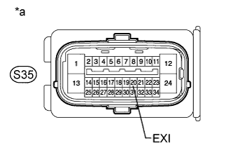
Text in Illustration *a Front view of wire harness connector
(to Skid Control ECU [Brake Actuator Assembly])
Disconnect the skid control ECU (brake actuator assembly) connector.
-
Measure the voltage according to the value(s) in the table below.
Standard Voltage Tester Connection Condition Specified Condition S35-20 (EXI) - Body ground
-
Ignition switch ON
-
Transfer shift position H4
Below 1.5 V -
-
Connect the skid control ECU (brake actuator assembly) connector.
-
Set the vehicle to the 2WD state using the transfer shift lever.
-
Disconnect the skid control ECU (brake actuator assembly) connector.
-
Measure the voltage according to the value(s) in the table below.
Standard Voltage Tester Connection Condition Specified Condition S35-20 (EXI) - Body ground
-
Ignition switch ON
-
Transfer shift position H2
11 to 14 V -
NG 
CHECK HARNESS AND CONNECTOR (SKID CONTROL ECU - 4 WHEEL DRIVE CONTROL ECU AND 4WD DETECTION SWITCH) Click here
OK 
-
-
CHECK TEST MODE DTC
-
Switch the vehicle to Test Mode, check the H2 to H4 shift operation, and then check that DTC C1282 is cleared Click here.
Result Result Proceed to Test Mode DTC is cleared A Test Mode DTC is not cleared for LHD B for RHD C
B 
REPLACE BRAKE ACTUATOR ASSEMBLY Click here
C
REPLACE BRAKE ACTUATOR ASSEMBLY Click here
A 
USE SIMULATION METHOD TO CHECK Click here
-
-
CHECK HARNESS AND CONNECTOR (SKID CONTROL ECU - 4 WHEEL DRIVE CONTROL ECU AND 4WD DETECTION SWITCH)
-
Turn the ignition switch off.
-
Disconnect the skid control ECU (brake actuator assembly) connector.
-
Disconnect the 4WD detection switch (differential vacuum actuator assembly) connector.
-
Disconnect the 4 wheel drive control ECU connector.
-
Measure the resistance according to the value(s) in the table below.
Standard Resistance Tester Connection Condition Specified Condition S35-20 (EXI) - A3-3 (ADD) Always Below 1 Ω S35-20 (EXI) - F14-8 (ADD) Always Below 1 Ω S35-20 (EXI) - Body ground Always 10 kΩ or higher A3-4 (GND) - Body ground Always Below 1 Ω
NG
REPAIR OR REPLACE HARNESS OR CONNECTOR
OK
GO TO TRANSFER SYSTEM (PROBLEM SYMPTOMS TABLE) Click here
-