METER / GAUGE SYSTEM, Diagnostic DTC:B1500
| DTC Code | DTC Name |
|---|---|
| B1500 | Fuel Sender Open Detected |
DESCRIPTION
This DTC is stored when the combination meter assembly detects a fuel sender gauge assembly malfunction via a direct line.
| DTC No. | Detection Item | DTC Detection Condition | Trouble Area | Memory | Note |
|---|---|---|---|---|---|
| B1500 | Fuel Sender Open Detected | for 8AR-FTS (for Rear Heated Oxygen Sensor): When IG voltage is 9.5 V or more and the following condition is detected:
for 2GR-FKS and 8AR-FTS (for Rear Air Fuel Ratio Sensor): When IG voltage is 9.5 V or more and the following condition is detected:
|
|
- | - |
WIRING DIAGRAM
-
for 8AR-FTS (for Rear Heated Oxygen Sensor)
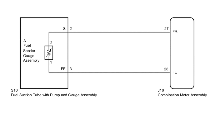
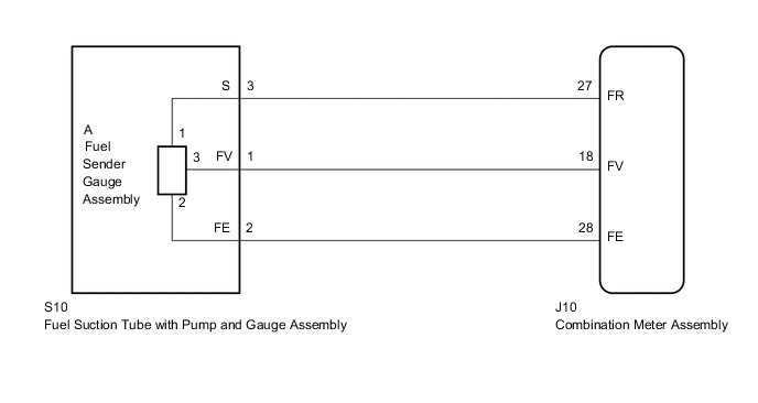
-
for 2GR-FKS and 8AR-FTS (for Rear Air Fuel Ratio Sensor)
PROCEDURE
-
READ VALUE USING GTS (FUEL INPUT)
-
Connect the GTS to the DLC3.
-
Turn the engine switch on (IG).
-
Turn the GTS on.
-
Enter the following menus: Body Electrical / Combination Meter / Data List.
-
Read the Data List according to the display on the GTS.
Body Electrical > Combination Meter > Data ListTester Display Measurement Item Range Normal Condition Diagnostic Note Fuel Input Fuel input Min.: 0 L, Max.: 127.5 L Fuel receiver gauge indicates F (1/1): 64.8 L
Fuel receiver gauge indicates 3/4: 50.4 L
Fuel receiver gauge indicates 1/2: 36.0 L
Fuel receiver gauge indicates 1/4: 21.6 L
Fuel receiver gauge indicates E (R): 7.2 L
Unit: Liter
Body Electrical > Combination Meter > Data ListTester Display Fuel Input Result Result Proceed to Fuel level data can be displayed on the GTS A Fuel level data cannot be displayed on the GTS (for 8AR-FTS (for Rear Heated Oxygen Sensor)) B Fuel level data cannot be displayed on the GTS (for 2GR-FKS and 8AR-FTS (for Rear Air Fuel Ratio Sensor)) C
A 
REPLACE COMBINATION METER ASSEMBLY Click here
C 
CHECK HARNESS AND CONNECTOR (COMBINATION METER ASSEMBLY - FUEL SUCTION TUBE WITH PUMP AND GAUGE ASSEMBLY) Click here
B 
-
-
CHECK HARNESS AND CONNECTOR (COMBINATION METER ASSEMBLY - FUEL SUCTION TUBE WITH PUMP AND GAUGE ASSEMBLY)
-
Disconnect the J10 combination meter assembly connector.
-
Disconnect the S10 fuel suction tube with pump and gauge assembly connector.
-
Measure the resistance according to the value(s) in the table below.
Standard Resistance Tester Connection Condition Specified Condition J10-27 (FR) - S10-2 (S) Always Below 1 Ω J10-28 (FE) - S10-3 (FE) Always Below 1 Ω J10-27 (FR) or S10-2 (S) - Body ground Always 10 kΩ or higher J10-28 (FE) or S10-3 (FE) - Body ground Always 10 kΩ or higher Result Proceed to OK NG
NG
REPAIR OR REPLACE HARNESS OR CONNECTOR
OK
-
-
INSPECT FUEL SENDER GAUGE ASSEMBLY
-
Remove the fuel sender gauge assembly.
-
Inspect the fuel sender gauge assembly.
Result Proceed to OK NG
NG
REPLACE FUEL SENDER GAUGE ASSEMBLY Click here
OK
-
-
INSPECT FUEL SUCTION TUBE WITH PUMP AND GAUGE ASSEMBLY
-
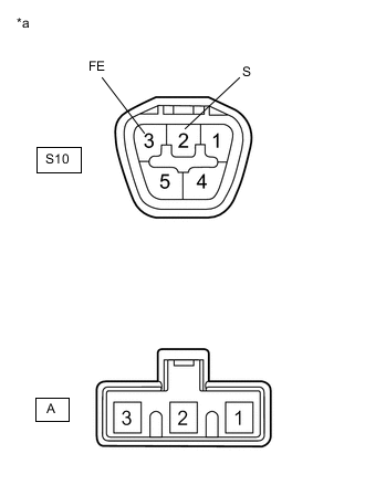
*a Component without harness connected
(Fuel Suction Tube with Pump and Gauge Assembly)
Measure the resistance according to the value(s) in the table below.
Standard Resistance Tester Connection Condition Specified Condition S10-2 (S) - A-2 Always Below 1 Ω S10-3 (FE) - A-1 Always Below 1 Ω Result Proceed to OK NG
OK
REPLACE COMBINATION METER ASSEMBLY Click here
NG
REPLACE FUEL SUCTION TUBE WITH PUMP AND GAUGE ASSEMBLY Click here
-
-
CHECK HARNESS AND CONNECTOR (COMBINATION METER ASSEMBLY - FUEL SUCTION TUBE WITH PUMP AND GAUGE ASSEMBLY)
-
Disconnect the J10 combination meter assembly connector.
-
Disconnect the S10 fuel suction tube with pump and gauge assembly connector.
-
Measure the resistance according to the value(s) in the table below.
Standard Resistance Tester Connection Condition Specified Condition J10-27 (FR) - S10-3 (S) Always Below 1 Ω J10-28 (FE) - S10-2 (FE) Always Below 1 Ω J10-18 (FV) - S10-1 (FV) Always Below 1 Ω J10-27 (FR) or S10-3 (S) - Body ground Always 10 kΩ or higher J10-28 (FE) or S10-2 (FE) - Body ground Always 10 kΩ or higher J10-18 (FV) or S10-1 (FV) - Body ground Always 10 kΩ or higher Result Proceed to OK NG
NG
REPAIR OR REPLACE HARNESS OR CONNECTOR
OK
-
-
INSPECT FUEL SENDER GAUGE ASSEMBLY
-
Remove the fuel sender gauge assembly.
for 2GR-FKS: Click here
for 8AR-FTS (for Rear Air Fuel Ratio Sensor): Click here
-
Inspect the fuel sender gauge assembly.
for 2GR-FKS: Click here
for 8AR-FTS (for Rear Air Fuel Ratio Sensor): Click here
OK Fuel sender gauge assembly is normal. Result Proceed to OK NG
NG
REPLACE FUEL SENDER GAUGE ASSEMBLY for 2GR-FKS: Click here
REPLACE FUEL SENDER GAUGE ASSEMBLY for 8AR-FTS (for Rear Air Fuel Ratio Sensor): Click hereOK
-
-
INSPECT FUEL SUCTION TUBE WITH PUMP AND GAUGE ASSEMBLY
-
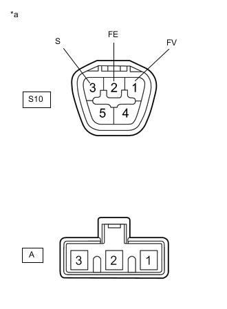
*a Component without harness connected
(Fuel Suction Tube with Pump and Gauge Assembly)
Measure the resistance according to the value(s) in the table below.
Standard Resistance Tester Connection Condition Specified Condition S10-1 (FV) - A-3 Always Below 1 Ω S10-2 (FE) - A-2 Always Below 1 Ω S10-3 (S) - A-1 Always Below 1 Ω S10-1 (FV) - S10-2 (FE)
or
A-3 - A-2
Always 10 kΩ or higher S10-2 (FE) - S10-3 (S)
or
A-2 - A1
Always 10 kΩ or higher S10-1 (FV) - S10-3 (S)
or
A-3 - A-1
Always 10 kΩ or higher Result Proceed to OK NG
OK
REPLACE COMBINATION METER ASSEMBLY Click here
NG
REPLACE FUEL SUCTION TUBE WITH PUMP AND GAUGE ASSEMBLY for 2GR-FKS: Click here
REPLACE FUEL SUCTION TUBE WITH PUMP AND GAUGE ASSEMBLY for 8AR-FTS (for Rear Air Fuel Ratio Sensor): Click here -