FRONT UPPER SUSPENSION ARM(for 4WD and Pre-Runner) REMOVAL

CAUTION / NOTICE / HINT
The necessary procedures (adjustment, calibration, initialization, or registration) that must be performed after parts are removed, installed, or replaced during the front upper suspension arm removal/installation are shown below.
| Necessary Procedure After Parts Removed/Installed/Replaced | ||||||||||||
|---|---|---|---|---|---|---|---|---|---|---|---|---|
|
Tech Tips
-
Use the same procedure for the RH and LH sides
-
The procedure listed below is for the LH side.
PROCEDURE
-
REMOVE FRONT WHEEL
-
DISCONNECT FRONT SPEED SENSOR LH
-
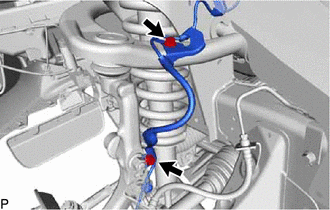
Remove the 2 bolts and disconnect the front speed sensor LH.
-
-
DISCONNECT FRONT STABILIZER LINK ASSEMBLY LH
-
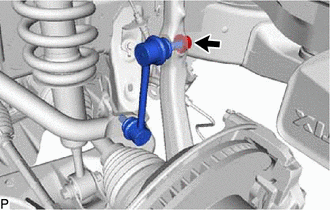
Remove the nut and disconnect the front stabilizer link assembly LH from the steering knuckle.
Tech Tips
If the ball joint turns together with the nut, use a 6 mm hexagon wrench to hold the stud in place.
-
-
REMOVE FRONT UPPER SUSPENSION ARM ASSEMBLY LH
-
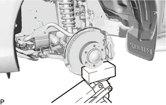
Support the lower arm with a jack.
-
Remove the clip and nut.
-
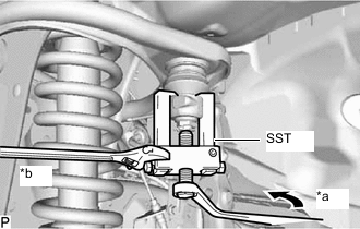
*a Turn *b Hold Using SST, disconnect the front upper ball joint from the steering knuckle.
- SST
- 09628-62011
-
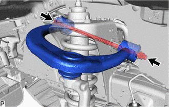
Remove the nut, 2 retainers and bolt.
-
Remove the front upper suspension arm assembly LH.
-
-
REMOVE FRONT UPPER SUSPENSION ARM BUSH LH
-
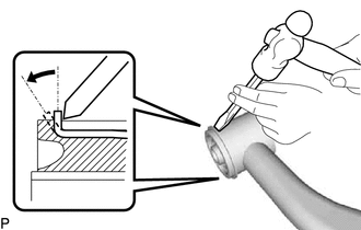
Using a hammer and chisel, strike and bend the entire flange of the bush as shown in the illustration.
-
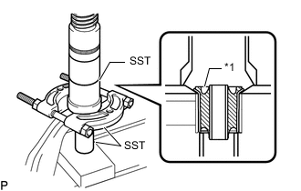
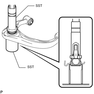
*1 Front Upper Suspension Arm Bush LH Using SST and a press, press out the front upper suspension arm bush LH.
- SST
- 09613-26010
- 09710-22021 ( 09710-01061 )
- 09950-00020
-
-
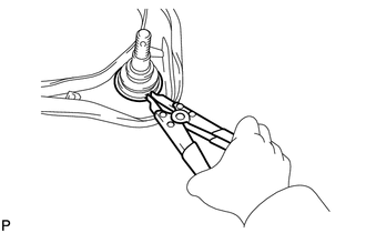
REMOVE UPPER BALL JOINT DUST COVER
-
Remove the dust cover set ring and upper ball joint dust cover from the front upper suspension arm assembly LH.
Note
-
Do not damage the upper ball joint dust cover.
-
If the upper ball joint dust cover is damaged, replace it.
-
-
-
REMOVE FRONT UPPER BALL JOINT
-
Using a snap ring expander, remove the snap ring.
-
Using SST and a press, press out the front upper ball joint.
- SST
- 09612-30012
- 09388-40010
-