AUTOMATIC TRANSMISSION ASSEMBLY INSTALLATION
CAUTION / NOTICE / HINT
CAUTION:
As the automatic transmission assembly with transfer is extremely heavy, the engine lifter may suddenly drop if the instructions listed in the repair manual are not followed.
Therefore, always follow the instructions listed in the repair manual when performing this procedure.
Note
This procedure includes the installation of small-head bolts. Refer to Small-Head Bolts of Basic Repair Hint to identify the small-head bolts.
PROCEDURE
-
INSTALL TRANSFER ASSEMBLY
Tech Tips
There is no need to remove this unless the transfer assembly is replaced.
-
INSTALL TORQUE CONVERTER ASSEMBLY
-
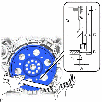
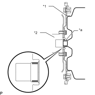
*1 Straightedge *2 Drive Plate *a Torque converter assembly contact surface of the drive plate *b Automatic transmission assembly with transfer contact surface of the engine assembly Using a vernier caliper and straightedge, measure the dimension A between the automatic transmission assembly with transfer contact surface of the engine assembly and the torque converter assembly contact surface of the drive plate.
Measurement Method B - C = A -
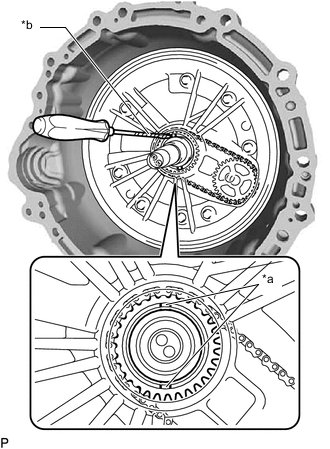
*a Protrusion of the Oil Pump Drive Sprocket *b Protective Tape Using a screwdriver with its tip wrapped with protective tape, align the oil pump drive sprocket so that it is perpendicular as shown in the illustration.
Note
Do not damage the front oil pump cover seal.
Tech Tips
Tape the screwdriver tip before use.
-
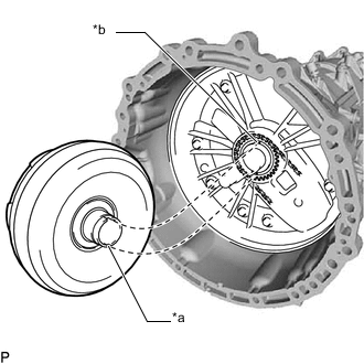
*a Cutout *b Protrusion of the Oil Pump Drive Sprocket Align the cutout on the torque converter assembly with the protrusion on the oil pump drive sprocket and attach the spline on the input shaft to the spline on the turbine liner.
Note
-
Install the torque converter assembly to the input shaft while keeping it horizontal.
-
Do not damage the front oil pump cover seal.
-
Make sure the cutout on the torque converter assembly and the protrusion on the oil pump drive sprocket are properly aligned.
-
-
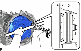
Using a vernier caliper and straightedge, measure the dimension D shown in the illustration and check that the dimension D is more than the dimension A, which was measured in the previous step.
Standard Dimension D = Dimension A + 1.0 mm (0.0394 in.) or more -
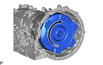

Rotates Smoothly Check that the torque converter assembly rotates smoothly.
-
-
INSTALL AUTOMATIC TRANSMISSION ASSEMBLY WITH TRANSFER
-
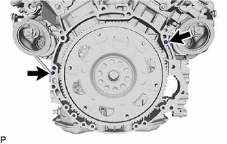

Knock Pin Confirm that the 2 knock pins are installed to the engine assembly and are not damaged.
-
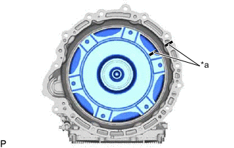
*a Matchmark Make sure that the matchmark is positioned as shown in the illustration.
-
*1 Drive Plate *2 Crankshaft *a Torque Converter Assembly Centerpiece 
Clutch Spline Grease Apply clutch spline grease to the surface the crankshaft that contacts the torque converter assembly centerpiece.
Clutch Spline Grease Toyota Genuine Clutch Spline Grease or equivalent Maximum Grease Amount Approximately 1 g (0.0353 oz.) -
Bolt A 
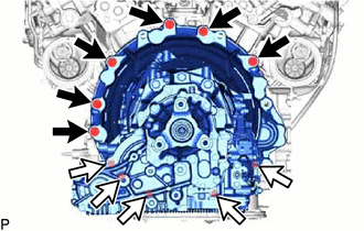
Bolt B While keeping the engine assembly and automatic transmission assembly with transfer horizontal, align the 2 knock pins with the holes in the automatic transmission assembly with transfer and install the automatic transmission assembly with transfer with the 10 bolts.
- Torque:
- for bolt A
- 71 N*m { 724 kgf*cm, 52 ft.*lbf }
- for bolt B
- 37 N*m { 377 kgf*cm, 27 ft.*lbf }
Note
-
Do not use excessive force when installing the automatic transmission assembly with transfer.
-
When mounting the automatic transmission assembly with transfer to the engine assembly, make sure to securely fit the 2 knock pins into the knock holes.
-
When tightening the bolts, make sure that the contact surfaces of the engine assembly and the automatic transmission assembly with transfer are in close contact with one another.
-
When installing the automatic transmission assembly with transfer, make sure that the oil cooler tube does not become damaged.
-
Check that the torque converter assembly rotates smoothly after installation of the automatic transmission assembly with transfer.
Tech Tips
Item Length Bolt A 50 mm (1.97 in.) Bolt B 43 mm (1.69 in.) -
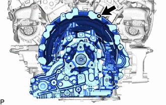
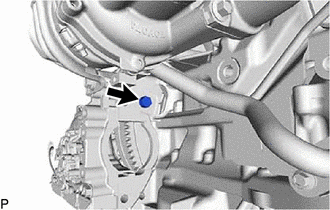
Install the stud bolt to the engine assembly.
- Torque:
- 9.5 N*m { 97 kgf*cm, 84 in.*lbf }
-
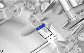
*a 38.0 to 46.0 mm (1.50 to 1.81 in.) Measure the installation dimension of the stud bolt in the illustration.
Standard Length 38.0 to 46.0 mm (1.50 to 1.81 in.)
-
-
INSTALL TRANSMISSION DYNAMIC DAMPER ASSEMBLY RH (for RHD)
-
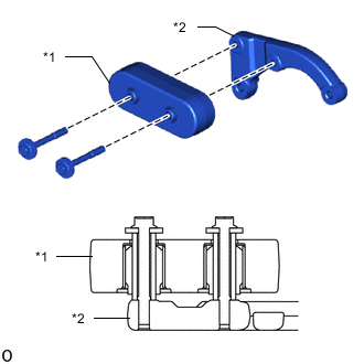
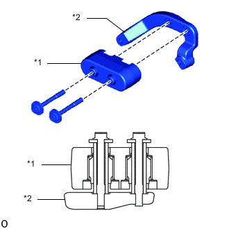
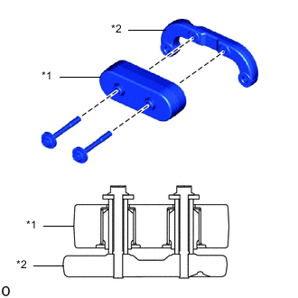
*1 Transmission Dynamic Damper *2 Transmission Dynamic Damper Bracket RH Install the transmission dynamic damper to the transmission dynamic damper bracket RH with the 2 new bolts as shown in the illustration.
- Torque:
- 20 N*m { 204 kgf*cm, 15 ft.*lbf }
-
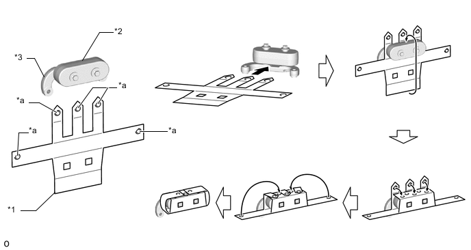
Install the transmission dynamic damper insulator to the transmission dynamic damper as shown in the illustration.
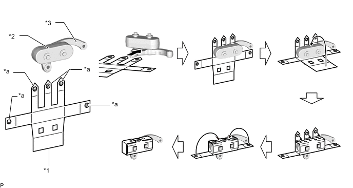
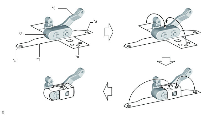
*1 Transmission Dynamic Damper Insulator *2 Transmission Dynamic Damper *3 Transmission Dynamic Damper Bracket RH - - *a Snap Fastener - - Note
-
Make sure that the transmission dynamic damper insulator does not become broken, rolled up, or frayed across the cross end during installation.
-
After wrapping the transmission dynamic damper insulator, securely attach the 5 snap fasteners.
-
-
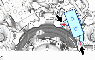
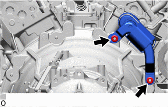
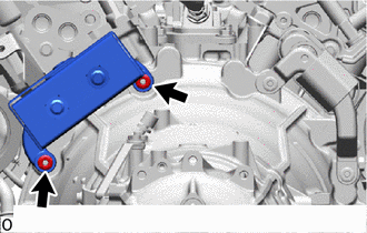
Install the transmission dynamic damper assembly RH to the automatic transmission assembly with the 2 new nuts.
- Torque:
- 17 N*m { 173 kgf*cm, 13 ft.*lbf }
Note
After installing the transmission dynamic damper assembly RH, make sure that it does not come loose from the snap fasteners.
-
-
INSTALL TRANSMISSION DYNAMIC DAMPER ASSEMBLY RH (for LHD)
-
*1 Transmission Dynamic Damper *2 Transmission Dynamic Damper Bracket RH Install the transmission dynamic damper to the transmission dynamic damper bracket RH with the 2 new bolts as shown in the illustration.
- Torque:
- 20 N*m { 204 kgf*cm, 15 ft.*lbf }
-
Install the transmission dynamic damper insulator to the transmission dynamic damper as shown in the illustration.
*1 Transmission Dynamic Damper Insulator *2 Transmission Dynamic Damper *3 Transmission Dynamic Damper Bracket RH - - *a Snap Fastener - - Note
-
Make sure that the transmission dynamic damper insulator does not become broken, rolled up, or frayed across the cross end during installation.
-
After wrapping the transmission dynamic damper insulator, securely attach the 3 snap fasteners.
-
-
Install the transmission dynamic damper assembly RH to the automatic transmission assembly with the 2 new nuts.
- Torque:
- 17 N*m { 173 kgf*cm, 13 ft.*lbf }
Note
After installing the transmission dynamic damper assembly RH, make sure that it does not come loose from the snap fasteners.
-
-
INSTALL TRANSMISSION DYNAMIC DAMPER ASSEMBLY LH (for LHD)
-
*1 Transmission Dynamic Damper *2 Transmission Dynamic Damper Bracket LH Install the transmission dynamic damper to the transmission dynamic damper bracket LH with the 2 new bolts as shown in the illustration.
- Torque:
- 20 N*m { 204 kgf*cm, 15 ft.*lbf }
-
Install the transmission dynamic damper insulator to the transmission dynamic damper as shown in the illustration.
*1 Transmission Dynamic Damper Insulator *2 Transmission Dynamic Damper *3 Transmission Dynamic Damper Bracket LH - - *a Snap Fastener - - Note
-
Make sure that the transmission dynamic damper insulator does not become broken, rolled up, or frayed across the cross end during installation.
-
After wrapping the transmission dynamic damper insulator, securely attach the 5 snap fasteners.
-
-
Install the transmission dynamic damper assembly LH to the automatic transmission assembly with the 2 new nuts.
- Torque:
- 17 N*m { 173 kgf*cm, 13 ft.*lbf }
Note
After installing the transmission dynamic damper assembly LH, make sure that it does not come loose from the snap fasteners.
-
-
INSTALL DRIVE PLATE AND TORQUE CONVERTER SETTING BOLT
-
Install the torque converter assembly to the drive plate and ring gear sub-assembly with the 6 drive plate and torque converter setting bolts.
- Torque:
- 64 N*m { 653 kgf*cm, 47 ft.*lbf }
Note
Start by tightening the positioning drive plate and torque converter setting bolt (black), and then uniformly tighten the remaining 5 drive plate and torque converter setting bolts (silver).
Tech Tips
Turn the crankshaft to a position where the drive plate and torque converter setting bolts can be installed, and install the drive plate and torque converter setting bolts while securing the crankshaft pulley bolt with a wrench.
-
Install the crankshaft damper sub-assembly.
-
-
INSTALL PROPELLER SHAFT HEAT INSULATOR
-
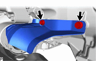
Install the propeller shaft heat insulator to the automatic transmission assembly with transfer with the 2 bolts.
- Torque:
- 10 N*m { 102 kgf*cm, 7 ft.*lbf }
-
-
INSTALL REAR ENGINE MOUNTING INSULATOR
-
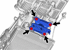
Install the rear engine mounting insulator to the automatic transmission assembly with transfer with the 4 bolts.
- Torque:
- 34 N*m { 347 kgf*cm, 25 ft.*lbf }
-
-
INSTALL ENGINE REAR MOUNTING MEMBER
-
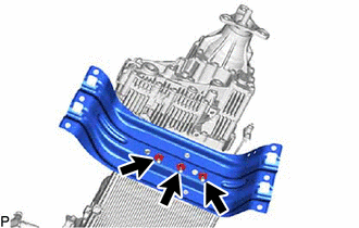
Install the engine rear mounting member to the automatic transmission assembly with transfer with the 3 nuts.
- Torque:
- 41 N*m { 418 kgf*cm, 30 ft.*lbf }
-
Bolt Nut and Spring Washer Connect the throttle link connecting rod assembly to the shift control actuator assembly with the nut, spring washer and 2 bolts.
- Torque:
- for bolt
- 12 N*m { 122 kgf*cm, 9 ft.*lbf }
- for nut
- 12.7 N*m { 130 kgf*cm, 9 ft.*lbf }
-
-
INSTALL OIL COOLER TUBE WITH OIL COOLER HOSE
-
Temporarily install the oil cooler tube with the 2 bolts.
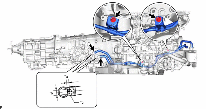
*a 2.0 to 7.0 mm (0.0787 to 0.276 in.) *b Permissible range for paint mark position *c Paint Mark - - -
Tighten the 2 bolts
- Torque:
- 22 N*m { 224 kgf*cm, 16 ft.*lbf }
-
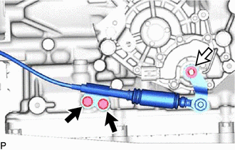
Connect the 2 oil cooler hoses to the automatic transmission assembly with transfer, and slide the 2 hose clips to secure the hoses.
Note
Adjust the oil cooler hose paint marks so that they are within the range shown in the illustration.
-
-
CONNECT WIRE HARNESS
-
Connect the wire harness to the automatic transmission assembly with transfer with the 4 bolts.
- Torque:
- 10 N*m { 102 kgf*cm, 7 ft.*lbf }
Wire Harness Connector Bolt 
Transmission Wire Connector Push Up Lever -
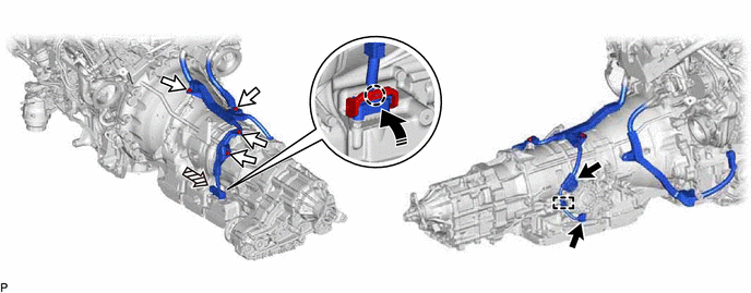
Connect the 2 wire harness connectors and wire harness clamp.
-
Connect the transmission wire connector.
Note
Push up the lever until the claw of the transmission wire connector makes a connection sound.
-
-
INSTALL FLYWHEEL HOUSING SIDE COVER
-
Install the flywheel housing side cover to the engine assembly.
-
-
INSTALL STARTER ASSEMBLY
-
w/ Stop and Start System:
-
w/o Stop and Start System:
-
-
INSTALL STARTER COVER
-
w/ Stop and Start System:
-
w/o Stop and Start System:
-
-
INSTALL FLYWHEEL HOUSING SIDE STAY
-
w/ Stop and Start System:
-
w/o Stop and Start System:
-
-
CONNECT NO. 2 ENGINE WIRE
-
w/ Stop and Start System:
-
w/o Stop and Start System:
-
-
INSTALL FRONT NO. 1 ENGINE MOUNTING BRACKET RH
-
INSTALL FRONT ENGINE MOUNTING INSULATOR
-
INSTALL FRONT FRAME ASSEMBLY
-
TEMPORARILY TIGHTEN FRONT PROPELLER SHAFT ASSEMBLY
-
FULLY TIGHTEN FRONT PROPELLER SHAFT ASSEMBLY
-
INSTALL CONVERTER ASSEMBLY RH
-
INSTALL CONVERTER ASSEMBLY LH
-
INSTALL NO. 1 VACUUM PIPE (w/ GPF)
-
INSTALL NO. 2 VACUUM PIPE (w/ GPF)
-
INSTALL NO. 2 TURBO INSULATOR
-
INSTALL NO. 4 TURBO INSULATOR
-
INSTALL AIR FUEL RATIO SENSOR (for Bank 2 Sensor 2)
-
INSTALL AIR FUEL RATIO SENSOR (for Bank 1 Sensor 2)
-
INSTALL AIR FUEL RATIO SENSOR (for Bank 2 Sensor 1)
-
INSTALL AIR FUEL RATIO SENSOR (for Bank 1 Sensor 1)
-
INSTALL ENGINE ASSEMBLY WITH TRANSMISSION
-
RESET MEMORY
-
CATALYST DETERIORATION CONFIRMATION DRIVING PATTERN
Tech Tips
Proceed to "CONFIRMATION DRIVING PATTERN".
-
w/ Canister Pump Module:
-
w/o Canister Pump Module:
-
-
ATF THERMAL DEGRADATION ESTIMATE RESET
Note
Approximately 50% or more of the ATF has been replaced during a repair of the transmission or a similar operation.