REAR DRIVE SHAFT ASSEMBLY REMOVAL

CAUTION / NOTICE / HINT
The necessary procedures (adjustment, calibration, initialization, or registration) that must be performed after parts are removed and installed, or replaced during rear drive shaft assembly removal/installation are shown below.
| Replaced Part or Performed Procedure | Necessary Procedure | Effect/Inoperative Function when Necessary Procedure not Performed | Link |
|---|---|---|---|
| Rear wheel alignment adjustment | Perform the following procedures in the order shown:
|
|
|
| Suspension, tires, etc. (The vehicle height changes because of suspension or tire replacement) |
|
|
|
| Rear television camera assembly optical axis (Back camera position setting) | Parking assist monitor system (w/ Parallel Parking Assist Function) | for Initialization: Click here for Calibration: Click here |
|
| Rear television camera assembly optical axis (Back camera position setting) | Parking assist monitor system (w/o Parallel Parking Assist Function) | for Initialization: Click here for Calibration: Click here |
|
|
Panoramic view monitor system | for Initialization: Click here for Calibration: Click here |
|
| Initialize headlight ECU sub-assembly LH |
|
||
| Gas leaks from exhaust system*2 | Inspection After Repair |
|
for 8AR-FTS: Click here for 2GR-FKS (w/ Canister Pump Module): Click here for 2GR-FKS (w/o Canister Pump Module): Click here |
*2: for RH Side
Tech Tips
-
Use the same procedure for the RH side and LH side.
-
The following procedure is for the LH side.
PROCEDURE
-
REMOVE TAIL EXHAUST PIPE ASSEMBLY (for RH Side)
for 8AR-FTS:
for 2GR-FKS:
-
REMOVE REAR WHEEL
-
REMOVE REAR AXLE SHAFT NUT
-
SEPARATE NO. 2 PARKING BRAKE WIRE ASSEMBLY
-
SEPARATE REAR SPEED SENSOR
-
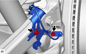
Remove the 2 bolts, sensor clamp and rear speed sensor from the rear axle carrier sub-assembly and rear trailing arm assembly.
Note
-
Keep the tip of the rear speed sensor and installation hole free of foreign matter.
-
Do not rotate or apply excessive force to the rear speed sensor when removing it from the rear axle carrier sub-assembly. Rotating or applying excessive force may result in damage to the rear speed sensor.
-
-
w/o AVS:
-
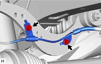
Remove the 2 bolts and separate the rear speed sensor from the rear upper control arm assembly.
-
-
w/ AVS:
-
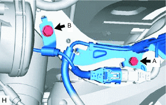
Remove the bolt (A) and separate the wire harness from the rear upper control arm assembly.
-
Remove the bolt (B) and separate the rear speed sensor from the rear upper control arm assembly.
-
-
-
SEPARATE REAR FLEXIBLE HOSE
-
REMOVE REAR SUSPENSION ARM COVER
-
REMOVE REAR STABILIZER LINK ASSEMBLY
-
REMOVE REAR COIL SPRING
-
REMOVE REAR LOWER COIL SPRING INSULATOR
-
SEPARATE REAR UPPER CONTROL ARM ASSEMBLY
-
REMOVE REAR NO. 1 SUSPENSION ARM ASSEMBLY
-
DRAIN DIFFERENTIAL OIL
-
REMOVE REAR DRIVE SHAFT ASSEMBLY
-
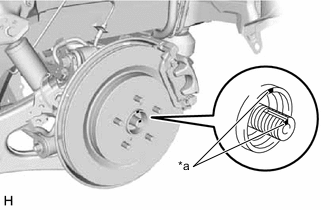
*a Matchmark Put matchmarks on the rear drive shaft assembly and rear axle hub and bearing assembly.
-
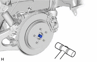
Using a plastic hammer, separate the rear drive shaft assembly from the rear axle hub and bearing assembly.
Tech Tips
If it is difficult to separate the rear drive shaft assembly from the rear axle hub and bearing assembly, tap the end of the rear drive shaft assembly using a brass bar and a hammer.
-
Separate the rear drive shaft assembly from the rear axle carrier sub-assembly.
Note
-
Do not damage the rear disc brake dust cover sub-assembly.
-
Do not damage the rear drive shaft outboard joint boot.
-
Do not drop the rear drive shaft assembly.
-
Do not push the rear axle carrier sub-assembly towards the outside of the vehicle any further than necessary.
-
-
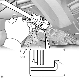
Using SST, remove the rear drive shaft assembly.
- SST
- 09520-01010
- 09520-24010 ( 09520-32040 )
Note
-
Do not damage the rear drive shaft oil seal.
-
Do not damage the rear drive shaft inboard joint boot.
-
Do not drop the rear drive shaft assembly.
-
When removing the rear drive shaft assembly, keep it level.
-
-
REMOVE REAR DRIVE SHAFT SNAP RING
-
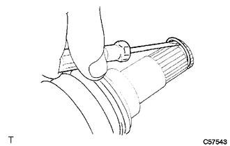
Using a screwdriver, remove the rear drive shaft snap ring.
-