МЕХАНИЧЕСКАЯ ТРАНСМИССИЯ В СБОРЕ УСТАНОВКА
-
INSTALL MANUAL TRANSMISSION UNIT ASSEMBLY
-
Align the input shaft with the clutch disc and install the transmission to the engine.
-
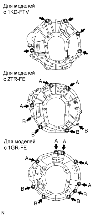
for 1KD-FTV:
Install the 5 bolts.
- Torque:
- 72 N*m { 730 kgf*cm, 53 ft.*lbf }
-
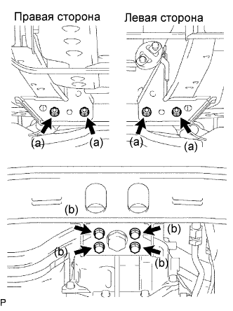
for 2TR-FE:
Install the 7 bolts.
- Torque:
- 72 N*m { 730 kgf*cm, 53 ft.*lbf, for bolt A }
- 37 N*m { 377 kgf*cm, 27 ft.*lbf, for bolt B }
-
for 1GR-FE:
Install the 9 bolts.
- Torque:
- 72 N*m { 730 kgf*cm, 53 ft.*lbf, for bolt A }
- 37 N*m { 377 kgf*cm, 27 ft.*lbf, for bolt B }
-
-
INSTALL STIFFENER PLATE (for 1KD-FTV)
-
Install the stiffener pate RH with the 4 bolts.
- Torque:
- 72 N*m { 730 kgf*cm, 53 ft.*lbf }
-
Install the stiffener pate LH with the 4 bolts.
- Torque:
- 72 N*m { 730 kgf*cm, 53 ft.*lbf }
-
-
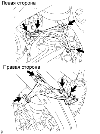
INSTALL EXHAUST MANIFOLD STAY (for 2TR-FE)
-
Install the exhaust manifold stay with the 3 bolts.
- Torque:
- 44 N*m { 449 kgf*cm, 32 ft.*lbf, for bolt A }
- 30 N*m { 306 kgf*cm, 22 ft.*lbf, for bolt B }
- 72 N*m { 730 kgf*cm, 53 ft.*lbf, for bolt C }
-
-
INSTALL REAR NO. 1 ENGINE MOUNTING INSULATOR
-
Install the mounting insulator with the 4 bolts.
- Torque:
- 44 N*m { 449 kgf*cm, 32 ft.*lbf }
-
-
INSTALL NO. 3 FRAME CROSSMEMBER SUB-ASSEMBLY
-
Install the frame crossmember with the 4 bolts and 4 nuts.
- Torque:
- 50 N*m { 510 kgf*cm, 37 ft.*lbf }
-
Install the 4 set bolts to the No. 1 engine mounting insulator rear.
- Torque:
- 17 N*m { 173 kgf*cm, 13 ft.*lbf }
-
-
INSTALL STARTER ASSEMBLY
for 2TR-FE 1.4 kW Type: Click here
for 2TR-FE 1.6 kW Type: Click here
for 2TR-FE 1.7 kW Type: Click here
for 1GR-FE: Click here
for 1KD-FTV 2.2 kW Type Bosch Made: Click here
for 1KD-FTV 2.2 kW Type Denso Made: Click here
for 2KD-FTV 2.2 kW Type: Click here
for 2KD-FTV 2.7 kW Type: Click here
-
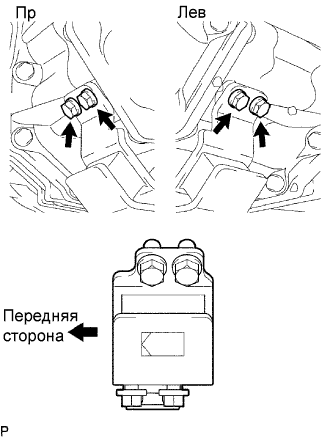
CONNECT CLUTCH RELEASE CYLINDER ASSEMBLY (for 1KD-FTV, 2TR-FE)
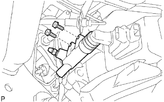
-
Install the clutch release cylinder with the 2 bolts.
- Torque:
- 12 N*m { 120 kgf*cm, 9 ft.*lbf }
-
-
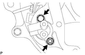
CONNECT CLUTCH RELEASE CYLINDER ASSEMBLY (for 1GR-FE)
-
Install the accumulator with the 3 bolts.
- Torque:
- 12 N*m { 120 kgf*cm, 9 ft.*lbf }
-
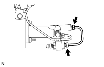
Using a union nut wrench, connect the 2 flexible hose tubes.
- Torque:
- 15 N*m { 153 kgf*cm, 11 ft.*lbf }
Note
Use the formula to calculate special torque values for situations where a union nut wrench is combined with a torque wrench Click here.
-
Install the clutch release cylinder assembly with the 2 bolts.
- Torque:
- 12 N*m { 120 kgf*cm, 9 ft.*lbf }
-
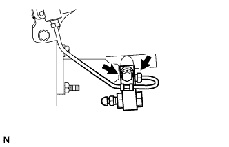
Using a union nut wrench, connect the flexible tube.
- Torque:
- 15 N*m { 153 kgf*cm, 11 ft.*lbf }
Note
Use the formula to calculate special torque values for situations where a union nut wrench is combined with a torque wrench Click here
-
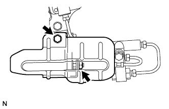
Install the 2 way with the bolt.
- Torque:
- 19 N*m { 194 kgf*cm, 14 ft.*lbf }
-
Using a union nut wrench, connect the flexible tube.
- Torque:
- 15 N*m { 153 kgf*cm, 11 ft.*lbf }
Note
Use the formula to calculate special torque values for situations where a union nut wrench is combined with a torque wrench Click here
-
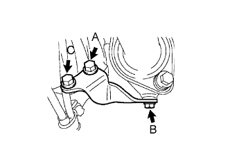
Install the release cylinder heat insulator with the bolt and nut.
- Torque:
- 12 N*m { 120 kgf*cm, 9 ft.*lbf }
-
-
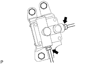
CONNECT WIRE HARNESS
-
Connect the back-up light switch connector and speedometer sensor connector.
-
-
INSTALL FRONT EXHAUST PIPE ASSEMBLY
for 2TR-FE: Click here
for 1GR-FE: Click here
for 1KD-FTV: Click here
for 2KD-FTV: Click here
for 2KD-FTV for DPF: Click here
-
INSTALL REAR PROPELLER SHAFT ASSEMBLY
for TSAM Made: Click here
for TMT Made: Click here
-
INSTALL NO. 2 FRAME CROSSMEMBER SUB-ASSEMBLY
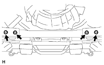
-
Install the frame crossmember with the 4 bolts and 4 nuts.
- Torque:
- 50 N*m { 510 kgf*cm, 37 ft.*lbf }
-
-
ADD MANUAL TRANSMISSION OIL
-
Установите автомобиль на ровной поверхности.
-
Снимите пробку наливного отверстия и прокладку.
-
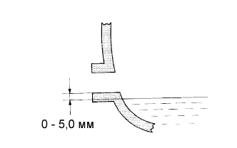
Убедитесь в том, что уровень масла отстоит от нижнего края отверстия для заливной пробки на 0-5 мм (0-0,20 дюйма).
Если результат не соответствует требованиям, добавьте трансмиссионную жидкость.
Класс масла по степени вязкости GL-4 Вязкость SAE 75W-90, 80W или 80W-90 Объем 2,6 л (2,7 кварты США, 2,3 английской кварты) Note
-
Чрезмерное или недостаточное количество масла может привести к неисправностям трансмиссии.
-
После корректировки уровня масла совершите пробную поездку на автомобиле, а затем снова проверьте уровень.
-
-
Если уровень масла мал, проверьте, нет ли утечек.
При обнаружении утечки отремонтируйте неисправный участок, чтобы устранить утечку. При необходимости замените поврежденные детали.
-
Установите новую прокладку и пробку наливного отверстия.
- Torque:
- 37 Н*м { 377 кгс*см, 27 фунт-сила-футов }
-
-
INSTALL NO. 2 ENGINE UNDER COVER
- Torque:
- 28 N*m { 286 kgf*cm, 21 ft.*lbf }
-
INSTALL NO. 1 ENGINE UNDER COVER
- Torque:
- 28 N*m { 286 kgf*cm, 21 ft.*lbf }
-
INSTALL FLOOR SHIFT SHIFT LEVER ASSEMBLY
-
Cover the shift lever cap with a cloth.
-
Press down on the shift lever cap and rotate it clockwise to install it.
Tech Tips
Apply MP grease to the tip of the shift lever.
-
-
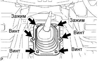
INSTALL SHIFT LEVER BOOT ASSEMBLY
-
Install the shift lever boot with the 4 screws and 2 clips.
-
w/o Console Box:
Install the floor carpet, front seat, front door scuff plate, etc.
-
-
INSTALL CONSOLE BOX ASSEMBLY
-
CONNECT CABLE TO NEGATIVE BATTERY TERMINAL
-
PERFORM INITIALIZATION
-
Perform initialization Click here.
Note
Certain systems need to be initialized after disconnecting and reconnecting the cable from the negative (-) battery terminal.
-
-
CHECK SRS WARNING LIGHT
-
BLEED AIR FROM CLUTCH PIPE LINE (for 1GR-FE)
-
CHECK FOR CLUTCH FLUID LEAKAGE (for 1GR-FE)