FRONT BRAKE (for TMT Made 2WD) INSTALLATION
Tech Tips
-
Use the same procedure for the RH and LH sides.
-
The procedure listed below is for the LH side.
-
INSTALL FRONT DISC
-
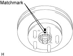
Align the matchmarks and install the disc.
Tech Tips
When replacing the disc with a new one, select the installation position where the disc has the smallest runout.
-
-
INSTALL FRONT DISC BRAKE CYLINDER MOUNTING LH
-
Install the disc brake cylinder mounting with the 2 bolts.
- Torque:
- 117 N*m { 1193 kgf*cm, 86 ft.*lbf }
-
-
INSTALL FRONT DISC BRAKE PAD SUPPORT PLATE
-
Install the 4 pad support plates to the cylinder mounting.
-
-
INSTALL PAD WEAR INDICATOR PLATE
-
Install the pad wear indicator plate to the inner lower side of the pad.
-
-
INSTALL FRONT ANTI-SQUEAL SHIM KIT
-
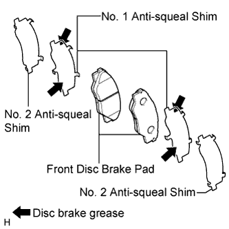
Apply a light coat of disc brake grease to both sides of each No. 1 anti-squeal shim.
-
Install the No. 1 anti-squeal shims and No. 2 anti-squeal shims to the pads.
Note
-
When replacing a worn pad, the shims must be replaced together with the pads.
-
Install the shims in the correct positions and directions as shown in the illustration.
-
-
-
INSTALL FRONT DISC BRAKE PAD
-
Install the 2 disc brake pads to the cylinder mounting.
Note
Make sure there is no oil or grease on the friction surfaces of the pads and disc.
-
-
INSTALL NO. 1 COLLAR
-
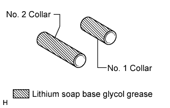
Apply a light coat of lithium soap base glycol grease to the No. 1 collar.
-
Install the No. 1 collar to the disc brake cylinder assembly.
-
-
INSTALL NO. 2 COLLAR
-
Apply a light coat of lithium soap base glycol grease to the No. 2 collar.
-
Install the No. 2 collar to the disc brake cylinder assembly.
-
-
INSTALL FRONT DISC BRAKE BUSH DUST BOOT
-
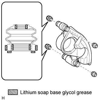
Apply a light coat of lithium soap base glycol grease to the entire circumference of 4 new front disc brake bush dust boots where they contact the disc brake cylinder, and the entire inner circumference of both ends of the boots.
Tech Tips
Apply at least 0.3 g (0.01 oz.) of lithium soap base glycol grease to the front disc brake bush dust boot.
Note
Apply a sufficient amount of lithium soap base glycol grease to the entire circumference of the front disc brake bush dust boot and disc brake cylinder contact surfaces.
-
Install the 4 front disc brake bush dust boots to the disc brake cylinder assembly.
-
-
INSTALL NO. 1 CYLINDER SLIDE BUSH
-
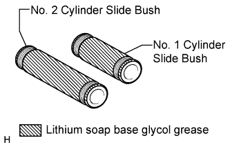
Apply a light coat of lithium soap base glycol grease to the No. 1 cylinder slide bush.
-
Install the No. 1 cylinder slide bush to the disc brake cylinder assembly.
-
-
INSTALL NO. 2 CYLINDER SLIDE BUSH
-
Apply a light coat of lithium soap base glycol grease to the No. 2 cylinder slide bush.
-
Install the No. 2 cylinder slide bush to the disc brake cylinder assembly.
-
-
INSTALL DISC BRAKE CYLINDER ASSEMBLY LH
-
Install the disc brake cylinder with the 2 bolts.
- Torque:
- 39 N*m { 400 kgf*cm, 29 ft.*lbf }
-
-
CONNECT FRONT FLEXIBLE HOSE
-
Install a new gasket and connect the flexible hose with a new union bolt.
- Torque:
- 29 N*m { 296 kgf*cm, 21 ft.*lbf }
Tech Tips
Insert the flexible hose lock securely into the lock hole in the cylinder.
-
-
FILL RESERVOIR WITH BRAKE FLUID
Fluid SAE J1703 or FMVSS No. 116 DOT 3 -
BLEED AIR FROM BRAKE MASTER CYLINDER
Tech Tips
If the master cylinder has been disassembled or if the reservoir becomes empty, bleed air from the master cylinder.
-
Using a union nut wrench, disconnect the 2 brake lines from the master cylinder.
-
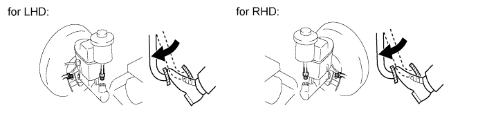
Slowly depress and hold the brake pedal.
-
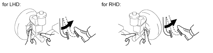
Cover the outer holes with your finger, and release the pedal.
-
Repeat the 2 previous steps 3 or 4 times.
-
Using a union nut wrench, connect the 2 brake lines to the master cylinder.
- Torque:
- 15 N*m { 155 kgf*cm, 11 ft.*lbf }
Note
Use the formula to calculate special torque values for situations where a union nut wrench is combined with a torque wrench Click here.
-
-
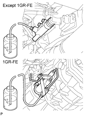
BLEED AIR FROM BRAKE LINE
-
Remove the bleeder plug cap.
-
Connect the vinyl tube to the bleeder plugs.
-
Depress the pedal several times, and then loosen the bleeder plug with the pedal depressed.
-
When fluid stops coming out, immediately tighten the bleeder plug. Then release the pedal.
-
Repeat the 2 previous steps until all the air in the brake fluid is gone.
-
Tighten the bleeder plug.
- Torque:
- for front brake
- 11 N*m { 110 kgf*cm, 8 ft.*lbf }
- for rear brake (2WD)
- 11 N*m { 112 kgf*cm, 8 ft.*lbf }
- for rear brake (4WD and Pre-Runner)
- 10 N*m { 102 kgf*cm, 7 ft.*lbf }
-
Install the cap.
-
Bleed air from the brake line for each wheel by repeating the above procedures.
-
-
BLEED AIR FROM CLUTCH LINE (for Manual Transmission)
-
Remove the bleeder plug cap.
-
Connect the vinyl tube to the bleeder plug.
-
Depress the clutch pedal several times, and then loosen the bleeder plug with the pedal depressed.
-
At the point when fluid stops coming out, tighten the bleeder plug, and then release the clutch pedal.
-
Repeat the previous 2 steps until all the air in the fluid is completely bled out.
-
Tighten the bleeder plug.
- Torque:
- 11 N*m { 112 kgf*cm, 8 ft.*lbf }
-
Install the bleeder plug cap.
-
Check that all the air has been bled out of the clutch line.
-
-
CHECK BRAKE FLUID LEVEL IN RESERVOIR
-
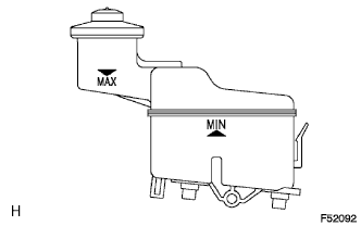
Check the fluid level.
If the brake fluid level is lower that the MIN line, check for leaks and inspect the disc brake pads. If necessary, refill the reservoir with brake fluid to the MAX line after repair or replacement.
Fluid SAE J1703 or FMVSS No. 116 DOT 3
-
-
CHECK FOR BRAKE FLUID LEAKAGE
-
INSTALL FRONT WHEEL
-
Install the front wheel.
- Torque:
- for steel wheel
- 152 N*m { 1550 kgf*cm, 112 ft.*lbf }
- for aluminum wheel
- 121 N*m { 1234 kgf*cm, 89 ft.*lbf }
-