SEAT BELT WARNING LIGHT(for Rear) REMOVAL
CAUTION / NOTICE / HINT
The necessary procedures (adjustment, calibration, initialization or registration) that must be performed after parts are removed, installed or replaced during the telltale light assembly removal/installation are shown below.
| Replacement Part or Procedure | Necessary Procedures | Effects / Inoperative when not Performed | Link |
|---|---|---|---|
| Disconnect cable from negative battery terminal | Drive the vehicle until stop and start control is permitted (approximately 5 to 60 minutes) | Stop and start system | |
| Memorize steering angle neutral point | Pre-crash safety system |
Tech Tips
-
Use the same procedure for RHD and LHD vehicles.
-
The procedure listed below is for LHD vehicles.
PROCEDURE
-
PRECAUTION
CAUTION:
Be sure to read Precaution thoroughly before servicing.
for Type A:
for Type B:

for Type C:
Note
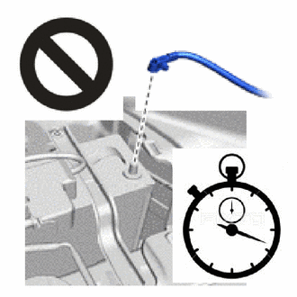
After turning the ignition switch off, waiting time may be required before disconnecting the cable from the negative (-) battery terminal. Therefore, make sure to read the disconnecting the cable from the negative (-) battery terminal notices before proceeding with work.
-
DISCONNECT CABLE FROM NEGATIVE BATTERY TERMINAL
CAUTION:
Wait at least 90 seconds after disconnecting the cable from the negative (-) battery terminal to disable the SRS system.
Note
When disconnecting the cable, some systems need to be initialized after the cable is reconnected.
-
REMOVE INSTRUMENT CLUSTER FINISH PANEL ASSEMBLY
-
REMOVE INSTRUMENT CLUSTER FINISH PANEL GARNISH ASSEMBLY
-
REMOVE NO. 1 INSTRUMENT PANEL BOX DOOR SUB-ASSEMBLY
-
REMOVE CONTROL KNOB SUB-ASSEMBLY (for Manual Cooler System)
-
REMOVE AIR INLET DAMPER CONTROL LEVER (for Manual Cooler System)
-
REMOVE INTEGRATION PANEL SUB-ASSEMBLY WITH AIR CONDITIONING CONTROL ASSEMBLY (for Manual Cooler System)
-
DISCONNECT DEFROSTER DAMPER CONTROL CABLE SUB-ASSEMBLY (for Manual Cooler System)
-
DISCONNECT AIR INLET DAMPER CONTROL CABLE SUB-ASSEMBLY (for Manual Cooler System)
-
REMOVE CONTROL KNOB SUB-ASSEMBLY (for Manual Air Conditioning System)
-
REMOVE AIR INLET DAMPER CONTROL LEVER (for Manual Air Conditioning System)
-
REMOVE INTEGRATION PANEL SUB-ASSEMBLY WITH AIR CONDITIONING CONTROL ASSEMBLY (for Manual Air Conditioning System)
-
DISCONNECT DEFROSTER DAMPER CONTROL CABLE SUB-ASSEMBLY (for Manual Air Conditioning System)
-
DISCONNECT AIR INLET DAMPER CONTROL CABLE SUB-ASSEMBLY (for Manual Air Conditioning System)
-
DISCONNECT AIR MIX DAMPER CONTROL CABLE SUB-ASSEMBLY (for Manual Air Conditioning System)
-
REMOVE AIR CONDITIONING CONTROL ASSEMBLY (for Automatic Air Conditioning System)
-
REMOVE CENTER INSTRUMENT CLUSTER FINISH PANEL ASSEMBLY
-
REMOVE TELLTALE LIGHT ASSEMBLY
-
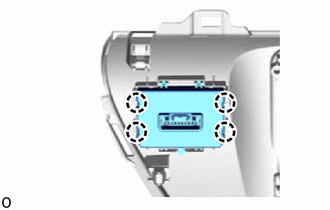
for LHD:
Detach the 4 claws and remove the telltale light assembly.
-
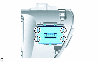
for RHD:
Detach the 4 claws and remove the telltale light assembly.
-