REAR DRIVE SHAFT ASSEMBLY INSTALLATION

CAUTION / NOTICE / HINT
Tech Tips
-
Use the same procedure for the RH side and LH side.
-
The following procedure is for the LH side.
PROCEDURE
-
INSTALL REAR DRIVE SHAFT SNAP RING
-
Install a new rear drive shaft snap ring.
Note
Face the end gap of the rear drive shaft snap ring downward.
-
-
INSTALL REAR DRIVE SHAFT ASSEMBLY
-
Coat the splines of the rear drive shaft inboard joint assembly with Toyota genuine differential gear oil LT 75W-85 GL-5 or equivalent.
-
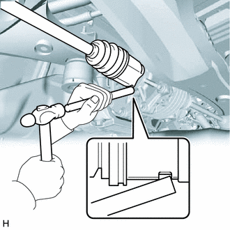
Align the inboard joint splines, and using a brass bar and a hammer, install the rear drive shaft assembly.
Note
-
Face the end gap of the rear drive shaft snap ring downward.
-
Do not damage the rear drive shaft oil seal.
-
Do not damage the rear drive shaft inboard joint boot.
-
Make sure to center the rear drive shaft assembly during installation to prevent damage to the rear drive shaft snap ring.
Tech Tips
Confirm whether the drive shaft is securely driven in by checking the reaction force and sound.
-
-
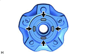

Toyota Body Grease W Apply 0.1 to 0.3 g (0.00353 to 0.0105 oz) of Toyota Body Grease W to each of the 4 areas shown in the illustration.
-
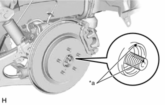
*a Matchmark Align the matchmarks and install the rear drive shaft assembly to the rear axle hub and bearing assembly.
Note
-
Do not damage the rear disc brake dust cover sub-assembly.
-
Do not damage the rear drive shaft outboard joint boot.
-
Check that there is no foreign matter on the contact surfaces.
-
Do not push the rear axle carrier sub-assembly towards the outside of the vehicle any further than necessary.
-
-
-
TEMPORARILY INSTALL REAR NO. 1 SUSPENSION ARM ASSEMBLY
-
CONNECT REAR UPPER CONTROL ARM ASSEMBLY
-
INSTALL REAR LOWER COIL SPRING INSULATOR
-
INSTALL REAR COIL SPRING
-
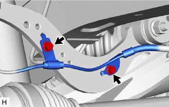
INSTALL REAR STABILIZER LINK ASSEMBLY
-
INSTALL REAR FLEXIBLE HOSE
-
INSTALL REAR SPEED SENSOR
-
w/o AVS:
-
Install the rear speed sensor to the rear upper control arm assembly with the 2 bolts.
- Torque:
- 8.5 N*m { 87 kgf*cm, 75 in.*lbf }
Note
Do not twist the rear speed sensor wire harness when installing it.
-
-
w/ AVS:
-
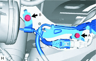
Install the wire harness to the rear upper control arm assembly with the bolt (A).
- Torque:
- 8.5 N*m { 87 kgf*cm, 75 in.*lbf }
Note
Do not twist the wire harness when installing it.
-
Install the rear speed sensor to the rear upper control arm assembly with the bolt (B).
- Torque:
- 8.5 N*m { 87 kgf*cm, 75 in.*lbf }
Note
Do not twist the rear speed sensor wire harness when installing it.
-
-
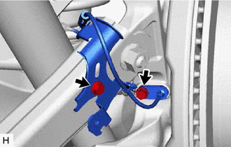
Install the rear speed sensor and sensor clamp to the rear axle carrier sub-assembly and rear trailing arm assembly with the 2 bolts.
- Torque:
- 8.5 N*m { 87 kgf*cm, 75 in.*lbf }
Note
-
Keep the tip of the rear speed sensor and installation hole free of foreign matter.
-
Firmly insert the rear speed sensor body into the rear axle carrier sub-assembly before tightening the bolt.
-
After installing the rear speed sensor to the rear axle carrier sub-assembly, make sure that there is no clearance between the rear speed sensor stay and rear axle carrier sub-assembly. Also make sure that no foreign matter is stuck between the parts.
-
Do not twist the rear speed sensor wire harness when installing it.
-
-
INSTALL NO. 2 PARKING BRAKE WIRE ASSEMBLY
-
INSTALL REAR AXLE SHAFT NUT
-
Clean the threaded parts on the rear drive shaft assembly and a new rear axle shaft nut using non-residue solvent.
Note
-
Be sure to perform this work even when using a new rear drive shaft assembly.
-
Keep the threaded parts free of oil and foreign matter.
-
-
Using a 30 mm deep socket wrench, temporarily install the rear axle shaft nut.
- Torque:
- 294 N*m { 2998 kgf*cm, 217 ft.*lbf }
Tech Tips
Keep depressing the brake pedal to prevent the rear drive shaft assembly from rotating.
-
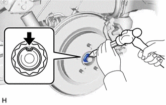
Using a chisel and hammer, stake the rear axle shaft nut.
-
-
STABILIZE SUSPENSION
-
INSTALL REAR NO. 1 SUSPENSION ARM ASSEMBLY
-
INSTALL REAR WHEEL
-
INSTALL REAR NO. 2 SUSPENSION ARM ASSEMBLY
-
INSTALL REAR SUSPENSION ARM COVER
-
INSTALL TAIL EXHAUST PIPE ASSEMBLY (for RH Side)
for 8AR-FTS:
for 2GR-FKS:
-
ADD DIFFERENTIAL OIL
-
INSPECT FOR DIFFERENTIAL OIL LEAK
-
INSPECT FOR EXHAUST GAS LEAK (for RH Side)
for 8AR-FTS:
for 2GR-FKS:
-
INSPECT AND ADJUST REAR WHEEL ALIGNMENT
-
CHECK FOR SPEED SENSOR SIGNAL
-
PERFORM INITIALIZATION
-
Intelligent clearance sonar system:
-
LEXUS parking assist-sensor system (w/ Intelligent Clearance Sonar System):
-
Parking assist monitor system (w/ Parallel Parking Assist Function):
for Initialization: Click here
for Calibration: Click here
-
Panoramic view monitor system (w/o Parallel Parking Assist Function):
for Initialization: Click here
for Calibration: Click here
-
Panoramic view monitor system:
for Initialization: Click here
for Calibration: Click here
-
Adaptive high beam system:
-
Automatic headlight beam level control system:
-