PROPELLER SHAFT ASSEMBLY REMOVAL

PROCEDURE
-
REMOVE NO. 2 ENGINE UNDER COVER
for 8AR-FTS:
for 2GR-FKS:
-
REMOVE FRONT FLOOR COVER LH
for 8AR-FTS:
for 2GR-FKS:
-
REMOVE FRONT CENTER FLOOR COVER
for 8AR-FTS:
for 2GR-FKS (w/ Canister Pump Module):
for 2GR-FKS (w/o Canister Pump Module):
-
REMOVE WIRING HARNESS CLAMP BRACKET
-
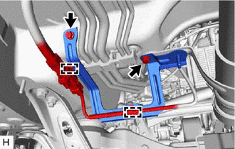
Disengage the 2 clamps.
-
Remove the 2 bolts and wiring harness clamp bracket.
-
-
REMOVE PROPELLER SHAFT GUARD (for Front Side)
-
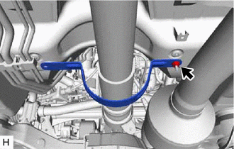
Remove the nut and propeller shaft guard.
-
-
REMOVE PROPELLER SHAFT GUARD (for Rear Side)
-
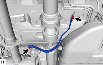
Remove the 2 bolts and propeller shaft guard.
-
-
REMOVE PROPELLER WITH CENTER BEARING SHAFT ASSEMBLY
-
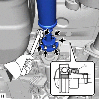
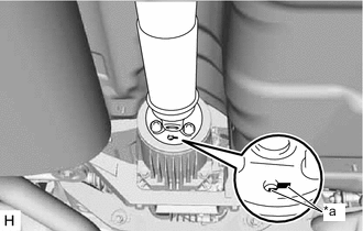
*a Piece of Cloth Using a 6 mm hexagon socket wrench, loosen the 6 cross groove joint set bolts 180°.
Note
-
Put a piece of cloth or equivalent into the inside of the universal joint cover so that the boot does not touch the inside of the universal joint cover.
-
Do not remove the cross groove joint set bolts.
-
-
*a Matchmark Put matchmarks on the electro magnetic control coupling sub-assembly and propeller with center bearing shaft assembly.
-
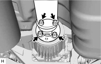
Remove the 4 nuts and 4 washers.
-
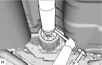
Using a brass bar and a hammer, separate the propeller with center bearing shaft assembly.
Note
Use wire or an equivalent tool to keep the propeller with center bearing shaft assembly.
-
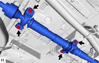
Remove the 4 bolts and 4 center No. 2 support bearing washers.
Note
When removing the bolts and center No. 2 support bearing washers, do not apply excessive force to the universal joint.
-
Pull out the propeller with center bearing shaft assembly from the transfer assembly.
Note
-
When removing the propeller with center bearing shaft assembly, do not apply excessive force to the universal joint.
-
During and after the removal of the propeller with center bearing shaft assembly, keep the universal joint angle straight (within 15 degrees).
-
Be careful not to damage the transfer extension housing type T oil seal.
-
-
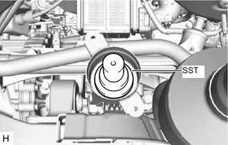
Insert SST into the transfer assembly to prevent oil leakage.
- SST
- 09325-20010
Note
Be careful not to damage the transfer extension housing type T oil seal.
-