REAR DOOR COURTESY SWITCH REMOVAL
CAUTION / NOTICE / HINT
The necessary procedures (adjustment, calibration, initialization or registration) that must be performed after parts are removed, installed or replaced during the rear courtesy light assembly removal/installation are shown below.
| Replacement Part or Procedure | Necessary Procedures | Effects / Inoperative when not Performed | Link |
|---|---|---|---|
| Disconnect cable from negative (-) battery terminal | Drive the vehicle until stop and start control is permitted (approximately 5 to 60 minutes) | Stop and start system | |
| Memorize steering angle neutral point | LKA/LDA system | ||
| Parking support brake system* | |||
| Pre-collision system | |||
| Adaptive high beam system | |||
Lighting system (EXT) |
|||
| Variable gear ratio steering system | |||
| Parking assist monitor system | |||
| Panoramic view monitor system | |||
| Initialize rear door sunshade system | Rear door sunshade system | ||
| Initialize power trunk lid system | Power trunk lid system |
Click here Click here
Tech Tips
-
Use the same procedure for the RH and LH sides.
-
The procedure listed below is for the LH side.
PROCEDURE
-
PRECAUTION
Note
After turning the engine switch off, waiting time may be required before disconnecting the cable from the negative (-) battery terminal. Therefore, make sure to read the disconnecting the cable from the negative (-) battery terminal notices before proceeding with work.
-
REMOVE LUGGAGE COMPARTMENT MAT SUB-ASSEMBLY
-
DISCONNECT CABLE FROM NEGATIVE BATTERY TERMINAL
CAUTION:
-
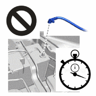
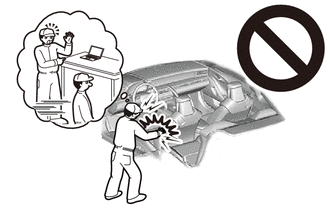
Wait at least 90 seconds after disconnecting the cable from the negative (-) battery terminal to disable the SRS system.
-
If the airbag deploys for any reason, it may cause a serious accident.
Note
When disconnecting the cable, some systems need to be initialized after the cable is reconnected.
-
-
REMOVE REAR SEAT CUSHION ASSEMBLY (for Fixed Seat Type)
-
REMOVE NO. 1 SEAT ARMREST CAP (for Fixed Seat Type)
-
REMOVE REAR SEATBACK ASSEMBLY (for Fixed Seat Type)
-
REMOVE REAR SEAT CUSHION LOCK HOOK (for Fixed Seat Type)
-
REMOVE REAR SEATBACK HOLDER (for Fixed Seat Type)
-
REMOVE REAR SEAT CUSHION ASSEMBLY LH (for Power Seat)
-
REMOVE REAR SEAT CUSHION LOCK HOOK (for Power Seat)
-
REMOVE REAR SEATBACK ASSEMBLY LH (for Power Seat)
-
REMOVE REAR DOOR SCUFF PLATE LH
-
REMOVE REAR SEAT SIDE GARNISH LH
-
REMOVE REAR DOOR COURTESY LIGHT SWITCH ASSEMBLY
-
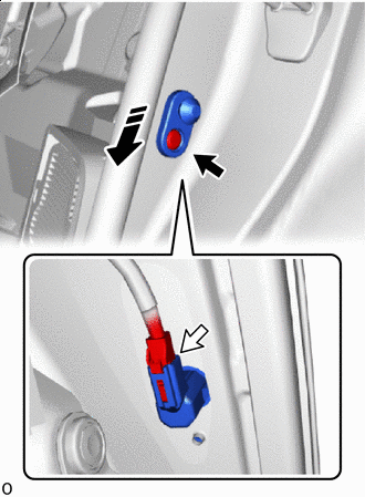

Remove in this Direction 
"TORX" Screw 
Connector Using a T30 "TORX" socket wrench, remove the "TORX" screw.
-
Disconnect the connector.
-
Pull out the direction indicated by the arrow shown in the illustration and remove the rear door courtesy light switch assembly.
-