TURBOCHARGER (for DPF) REMOVAL
-
PRECAUTION
Note
After turning the ignition switch off, waiting time may be required before disconnecting the cable from the battery terminal. Therefore, make sure to read the disconnecting the cable from the battery terminal notice before proceeding with work Click here.
-
DISCONNECT CABLE FROM NEGATIVE BATTERY TERMINAL
Note
When disconnecting the cable, some systems need to be initialized after the cable is reconnected Click here.
-
REMOVE FRONT EXHAUST PIPE ASSEMBLY
-
REMOVE INTERCOOLER ASSEMBLY
-
REMOVE NO. 1 ENGINE UNDER COVER
-
REMOVE NO. 2 ENGINE UNDER COVER
-
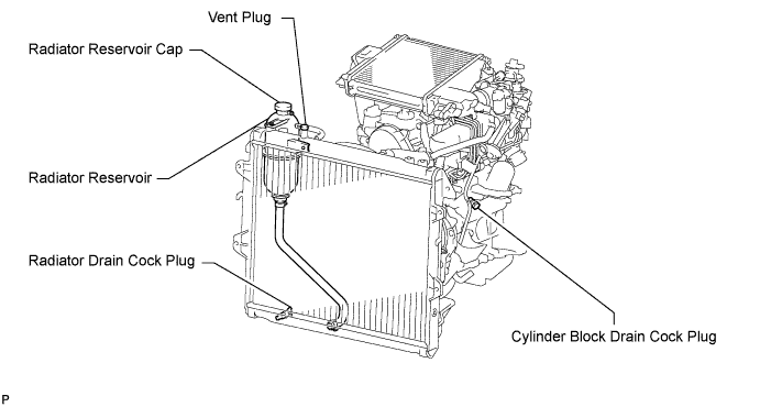
DRAIN ENGINE COOLANT
CAUTION:
Do not remove the radiator reservoir cap while the engine and radiator are still hot. Pressurized, hot engine coolant and steam may be released and cause serious burns.
-
Loosen the radiator drain cock plug.
Tech Tips
Collect the coolant in a container and dispose of it according to the regulations in your area.
-

Drain the coolant by removing the reservoir cap and, using a wrench, remove the vent plug.
-
Loosen the cylinder block drain cock plug.
-
-
REMOVE FRONT FENDER APRON SEAL UPPER
-
Remove the 5 clips and front fender apron seal upper.
-
-
REMOVE FRONT FENDER SEAL
-
Remove the 5 clips and front fender seal.
-
-
REMOVE AIR CLEANER ASSEMBLY
-
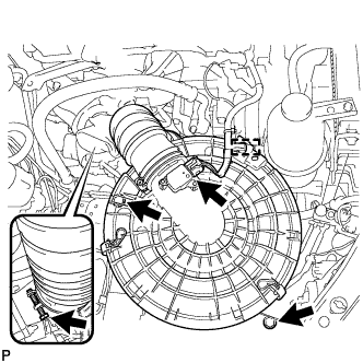
Detach the wire harness clamp and disconnect the mass air flow meter connector.
-
Loosen the hose clamp and disconnect No. 1 air cleaner hose from the compressor inlet elbow.
-
Remove the 2 bolts and air cleaner assembly together with the No. 1 air cleaner hose.
-
-
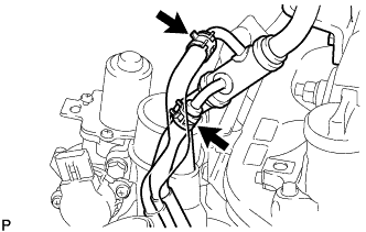
REMOVE VENTILATION PIPE
-
for Cold Area Specification Vehicles:
Disconnect the No. 12 water by-pass hose and No. 13 water by-pass hose.
-
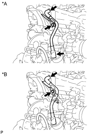
Text in Illustration *A except Cold Area Specification Vehicles *B for Cold Area Specification Vehicles Remove the bolt and ventilation pipe.
-
-
REMOVE COMPRESSOR INLET ELBOW
-
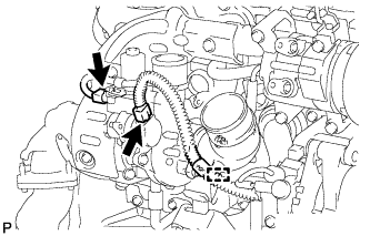
Disconnect the 2 connectors and detach the wire harness clamp.
-
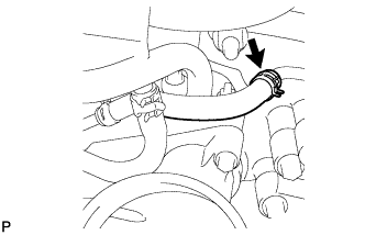
Disconnect the No. 1 turbo water hose.
-
Disconnect the No. 2 water by-pass hose.
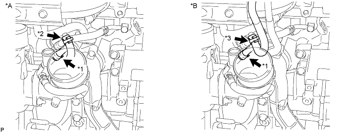
Text in Illustration *A except Cold Area Specification Vehicles *B for Cold Area Specification Vehicles *1 No. 2 Water By-pass Hose *2 No. 9 Water By-pass Hose *3 No. 13 Water By-pass Hose - - -
except Cold Area Specification Vehicles:
Disconnect the No. 9 water by-pass.
-
for Cold Area Specification Vehicles:
Disconnect the No. 13 water by-pass hose.
-
Remove the 2 nuts, compressor inlet elbow and gasket.
-
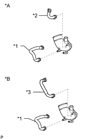
Text in Illustration *A except Cold Area Specification Vehicles *B for Cold Area Specification Vehicles *1 No. 7 Water By-pass Hose *2 No. 9 Water By-pass Hose *3 No. 12 Water By-pass Hose Remove the No. 7 water by-pass hose.
-
except Cold Area Specification Vehicles:
Remove the No. 9 water by-pass hose.
-
for Cold Area Specification Vehicles:
Remove the No. 12 water by-pass hose.
-
-
REMOVE NO. 1 TURBO INSULATOR
-
Remove the 2 bolts and No. 1 turbo insulator.
-
-
REMOVE NO. 1 EXHAUST MANIFOLD HEAT INSULATOR
-
Remove the bolt and No. 1 exhaust manifold heat insulator.
-
-
REMOVE NO. 2 EXHAUST MANIFOLD HEAT INSULATOR
-
Remove the 2 bolts and No. 2 exhaust manifold heat insulator.
-
-
REMOVE NO. 3 EXHAUST MANIFOLD HEAT INSULATOR
-
Remove the 2 bolts and No. 3 exhaust manifold heat insulator.
-
-
REMOVE TURBINE OUTLET ELBOW STAY
-
Detach the wire harness clamp and remove the bolt, nut and turbine outlet elbow stay.
-
-
REMOVE NO. 2 TURBINE OUTLET ELBOW
-
Remove the 3 nuts, No. 2 turbine outlet elbow and gasket.
-
-
DISCONNECT NO. 1 FUEL PIPE
-
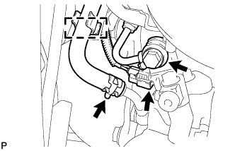
Detach the hose clamp and disconnect the No. 4 turbo water hose from the No. 4 water by-pass pipe.
-
Disconnect the exhaust fuel addition injector connector.
-
Remove the union bolt and gasket from the No. 1 fuel pipe.
-
Disconnect the No. 1 fuel pipe from the turbine outlet elbow.
-
-
REMOVE TURBINE OUTLET ELBOW
-
Disconnect the No. 3 turbo water hose from the No. 3 water by-pass pipe.
-
Remove the 3 nuts, turbine outlet elbow and gasket.
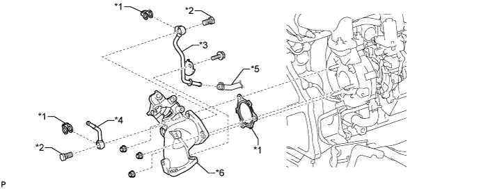
Text in Illustration *1 Gasket *2 Union Bolt *3 No. 3 Water By-pass Pipe *4 No. 4 Water By-pass Pipe *5 No. 3 Turbo Water Hose *6 Turbine Outlet Elbow -
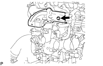
Remove the bolt, union bolt, gasket and No. 3 water by-pass pipe from the turbine outlet elbow.
-
Remove the union bolt, gasket and No. 4 water by-pass pipe from the turbine outlet elbow.
-
-
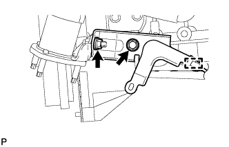
REMOVE TURBOCHARGER STAY
-
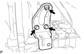
Remove the 2 bolts, nut and turbocharger stay.
-
-
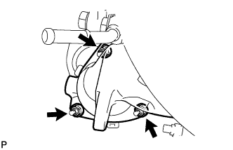
REMOVE TURBO OIL INLET PIPE SUB-ASSEMBLY
-
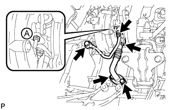
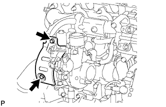
Remove the 2 bolts, 2 nuts, union bolt, turbo oil inlet pipe sub-assembly and 3 gaskets.
Note
Do not loosen the nut labeled A in the illustration.
-
-
REMOVE TURBOCHARGER SUB-ASSEMBLY
-
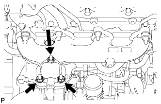
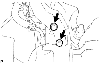
Remove the 3 nuts, turbocharger sub-assembly and gasket.
-
-
REMOVE NO. 1 TURBO WATER PIPE SUB-ASSEMBLY
-
Remove the No. 1 turbo water hose sub-assembly and No. 3 turbo water hose.
-
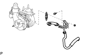
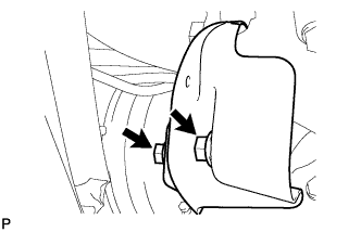
Remove the 2 nuts, bolt, No. 1 turbo water pipe sub-assembly and gasket.
-