CYLINDER HEAD GASKET INSTALLATION
CAUTION / NOTICE / HINT
Note
This procedure includes the installation of small-head bolts. Refer to Small-Head Bolts of Basic Repair Hint to identify the small-head bolts.
Tech Tips
Perform "Inspection After Repairs" after replacing the cylinder head sub-assembly RH or cylinder head sub-assembly LH.
-
w/ Canister Pump Module:
-
w/o Canister Pump Module:
PROCEDURE
-
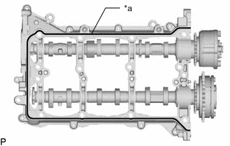
INSTALL CYLINDER HEAD GASKET RH
-
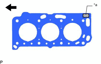
*a Lot No. 
Engine Front Place the cylinder head gasket RH on the cylinder block sub-assembly RH surface with the Lot No. stamp upward.
Note
-
Be careful of the installation direction.
-
Gently place the cylinder head sub-assembly RH in order not to damage the cylinder gasket RH with the bottom part of the cylinder head sub-assembly RH.
-
-
-
INSTALL CYLINDER HEAD SUB-ASSEMBLY RH
Tech Tips
Perform "Inspection After Repairs" after replacing the cylinder head sub-assembly RH.
-
w/ Canister Pump Module:
-
w/o Canister Pump Module:
-
Place the cylinder head sub-assembly RH on the cylinder block sub-assembly.
Note
Be careful not to allow oil to adhere to the bottom part of the cylinder head sub-assembly RH.
Tech Tips
The cylinder head set bolts are tightened in 3 progressive steps.
-
Apply a light coat of engine oil to the threads and under the heads of the cylinder head set bolts.
-
Bolt Length 140 mm (5.51 in.) 
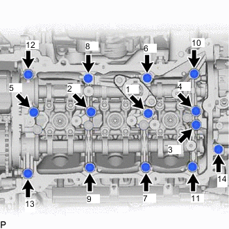
Bolt Length 150 mm (5.90 in.) Step 1:
-
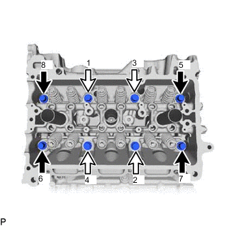
Using a 12 mm socket wrench, install and uniformly tighten the 8 cylinder head set bolts with the plate washers in several steps and in the sequence shown in the illustration.
- Torque:
- 90 N*m { 918 kgf*cm, 66 ft.*lbf }
-
-
Step 2:
-
Mark the front side of each cylinder head set bolt head with paint.
-
Tighten the cylinder head set bolts another 90°.
-
-
Step 3:
-
Tighten the cylinder head set bolts an additional 90°.
-
Check that the paint marks are now at a 180° angle to the front.
-
-
-
INSTALL CYLINDER HEAD GASKET LH
-
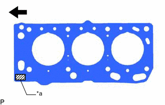
*a Lot No. Engine Front Place the cylinder head gasket sub-assembly LH on the cylinder block sub-assembly surface with the Lot No. stamp upward.
Note
-
Be careful of the installation direction.
-
Gently place the cylinder head sub-assembly LH in order not to damage the cylinder gasket LH with the bottom part of the cylinder head sub-assembly LH.
-
-
-
INSTALL CYLINDER HEAD SUB-ASSEMBLY LH
Tech Tips
Perform "Inspection After Repairs" after replacing the cylinder head sub-assembly LH.
-
w/ Canister Pump Module:
-
w/o Canister Pump Module:
-
Place the cylinder head sub-assembly LH on the cylinder block sub-assembly.
Note
Be careful not to allow oil to adhere to the bottom part of the cylinder head sub-assembly LH.
Tech Tips
The cylinder head set bolts are tightened in 3 progressive steps.
-
Apply a light coat of engine oil to the threads and under the heads of the cylinder head set bolts.
-
Bolt Length 140 mm (5.51 in.) Bolt Length 150 mm (5.90 in.) Step 1:
-
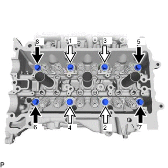
Using a 12 mm socket wrench, install and uniformly tighten the 8 cylinder head set bolts with the plate washers in several steps in the sequence shown in the illustration.
- Torque:
- 90 N*m { 918 kgf*cm, 66 ft.*lbf }
-
-
Step 2:
-
Mark the front side of each cylinder head set bolt head with paint.
-
Tighten the cylinder head set bolts another 90°.
-
-
Step 3:
-
Tighten the cylinder head set bolts an additional 90°.
-
Check that the paint marks are now at a 180° angle to the front.
-
-
-
INSTALL VALVE STEM CAP
-
Apply a light coat of engine oil to the valve stem caps.
-
Install the 24 valve stem caps to the cylinder head sub-assembly.
Note
Install the valve stem cap to the same place it was removed from.
-
-
INSTALL VALVE LASH ADJUSTER ASSEMBLY
-
Inspect the valve lash adjuster assembly.
-
Install the 24 valve lash adjuster assemblies to the cylinder head sub-assembly.
Note
Install the valve lash adjuster assembly to the same place it was removed from.
-
-
INSTALL VALVE ROCKER ARM SUB-ASSEMBLY
-
Apply engine oil to the valve lash adjuster assembly tips and valve stem cap ends.
-
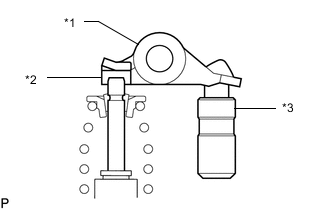
*1 Valve Rocker Arm Sub-assembly *2 Valve Stem Cap *3 Valve Lash Adjuster Assembly Install the 24 valve rocker arm sub-assemblies as shown in the illustration.
Note
Install the valve rocker arm sub-assembly to the same place it was removed from.
-
-
INSTALL INTAKE CAMSHAFT SUB-ASSEMBLY LH
-
Apply a light coat of engine oil to the intake camshaft sub-assembly LH journals and camshaft housing sub-assembly LH.
-
Install the intake camshaft sub-assembly LH to the camshaft housing sub-assembly LH.
-
-
INSTALL EXHAUST CAMSHAFT SUB-ASSEMBLY LH
-
Apply a light coat of engine oil to the exhaust camshaft sub-assembly LH journals and camshaft housing sub-assembly LH.
-
Install the No. 2 chain sub-assembly to the intake camshaft sub-assembly LH and exhaust camshaft sub-assembly LH.
-
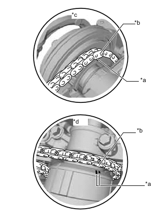
*a Timing Mark *b Mark Plate *c Intake Side *d Exhaust Side Align the mark plates (Pink) with the timing marks of the camshaft timing gear assemblies as shown in the illustration.
-
Install the exhaust camshaft sub-assembly LH to the camshaft housing sub-assembly LH.
-
-
INSTALL CAMSHAFT HOUSING SUB-ASSEMBLY LH
-
Apply engine oil to the camshaft bearing caps.
-
Make sure on the camshaft bearing caps and place each in the proper position and direction.
-
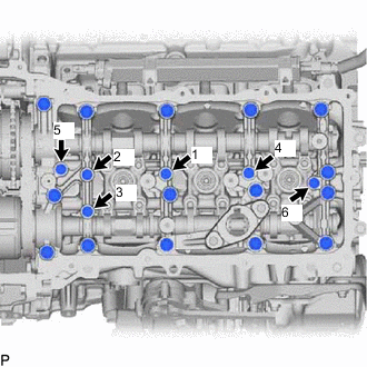
Install and tighten the 6 bolts in the order shown in the illustration.
- Torque:
- 16 N*m { 163 kgf*cm, 12 ft.*lbf }
Tech Tips
Bolt Length 40 mm (1.57 in.)
-
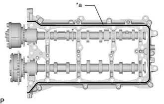
*a Diameter 3.0 to 4.0 mm (0.118 to 0.158 in.) 
Seal Packing Apply seal packing in a continuous line as shown in the illustration.
Seal packing Toyota Genuine Seal Packing Black, Three Bond 1207B or equivalent Note
-
Remove any oil from the contact surface.
-
Install the camshaft housing sub-assembly LH within 3 minutes.
-
Do not start the engine for at least 2 hours after installation.
-
-
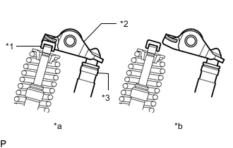
*1 Valve Stem Cap *2 Valve Rocker Arm Sub-assembly *3 Valve Lash Adjuster Assembly *a CORRECT *b INCORRECT Make sure that the valve rocker arm sub-assembly is installed as shown in the illustration.
-
Install the camshaft housing sub-assembly LH to the cylinder head sub-assembly LH.
-
-
INSTALL CAMSHAFT BEARING CAP (for Bank 2)
-
Install the fuel pump lifter housing sub-assembly LH.
-
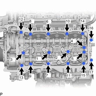
Install the camshaft housing sub-assembly LH and tighten the 17 bolts in the order shown in the illustration.
- Torque:
- 28 N*m { 286 kgf*cm, 21 ft.*lbf }
Standard Bolt Item Length Camshaft housing sub-assembly LH install bolt 40 mm (1.57 in.) Bearing cap bolt 65 mm (2.56 in.) Note
-
If any of the bolts are loosened during installation, remove the camshaft housing sub-assembly LH, clean the installation surfaces, and reapply seal packing.
-
If the camshaft housing sub-assembly LH is removed because any of the bolts are loosened during installation, make sure that the previously applied seal packing does not enter any oil passages.
-
Remove any protruding seal packing black.
-
-
INSTALL INTAKE CAMSHAFT SUB-ASSEMBLY RH
-
Apply a light coat of engine oil to the intake camshaft sub-assembly RH journals and camshaft housing sub-assembly RH.
-
Install the intake camshaft sub-assembly RH to the camshaft housing sub-assembly RH.
-
-
INSTALL EXHAUST CAMSHAFT SUB-ASSEMBLY RH
-
Apply a light coat of engine oil to the exhaust camshaft sub-assembly RH journals and camshaft housing sub-assembly RH.
-
Install the No. 2 chain sub-assembly to the intake camshaft sub-assembly RH and exhaust camshaft sub-assembly RH.
-
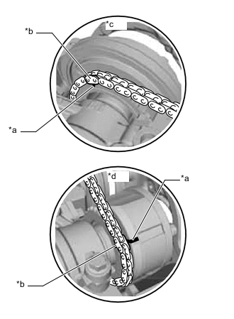
*a Timing Mark *b Mark Plate *c Intake Side *d Exhaust Side Align the mark plates (Pink) with the timing marks of the camshaft timing gear assemblies as shown in the illustration.
-
Install the exhaust camshaft sub-assembly RH to the camshaft housing sub-assembly RH.
-
-
INSTALL CAMSHAFT HOUSING SUB-ASSEMBLY RH
-
Apply engine oil to the camshaft bearing caps.
-
Make sure on the camshaft bearing caps and place each in the proper position and direction.
-
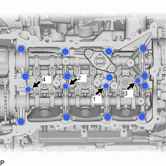
Install and tighten the 4 bolts in the order shown in the illustration.
- Torque:
- 16 N*m { 163 kgf*cm, 12 ft.*lbf }
Tech Tips
Bolt Length 40 mm (1.57 in.)
-
*a Diameter 3.0 to 4.0 mm (0.118 to 0.158 in.) Seal Packing Apply seal packing in a continuous line as shown in the illustration.
Seal packing Toyota Genuine Seal Packing Black, Three Bond 1207B or equivalent Note
-
Remove any oil from the contact surface.
-
Install the camshaft housing sub-assembly RH within 3 minutes.
-
Do not start the engine for at least 2 hours after installation.
-
-
*1 Valve Stem Cap *2 No. 1 Valve Rocker Arm Sub-assembly *3 Valve Lash Adjuster Assembly *a CORRECT *b INCORRECT Make sure that the valve rocker arm sub-assembly is installed as shown in the illustration.
-
Install the camshaft housing sub-assembly RH to the cylinder head sub-assembly RH.
-
-
INSTALL CAMSHAFT BEARING CAP (for Bank 1)
-
Install the fuel pump lifter housing sub-assembly RH.
-
Install the camshaft housing sub-assembly RH and tighten the 14 bolts in the order shown in the illustration.
- Torque:
- 28 N*m { 286 kgf*cm, 21 ft.*lbf }
Standard Bolt Item Length Camshaft housing sub-assembly RH install bolt 40 mm (1.57 in.) Bearing cap bolt 65 mm (2.56 in.) Note
-
If any of the bolts are loosened during installation, remove the camshaft housing sub-assembly RH, clean the installation surfaces, and reapply seal packing.
-
If the camshaft housing sub-assembly RH is removed because any of the bolts are loosened during installation, make sure that the previously applied seal packing does not enter any oil passages.
-
Remove any protruding seal packing black.
-
-
INSTALL VACUUM PUMP ASSEMBLY
-
INSTALL TIMING CHAIN COVER ASSEMBLY
-
INSTALL CRANKSHAFT TIMING GEAR OR SPROCKET
-
INSTALL NO. 2 CHAIN VIBRATION DAMPER
-
INSTALL NO. 1 CHAIN VIBRATION DAMPER
-
INSTALL IDLE SPROCKET ASSEMBLY
-
INSTALL NO. 1 CHAIN SUB-ASSEMBLY
-
INSTALL CHAIN TENSIONER SLIPPER
-
INSTALL NO. 1 CHAIN TENSIONER ASSEMBLY
-
INSPECT VALVE TIMING
-
INSTALL OIL PUMP DRIVE CHAIN SUB-ASSEMBLY
-
INSTALL TIMING CHAIN OR BELT COVER SUB-ASSEMBLY
-
INSTALL NO. 2 TURBOCHARGER SUB-ASSEMBLY
-
INSTALL NO. 1 TURBOCHARGER SUB-ASSEMBLY
-
INSTALL DIRECT FUEL INJECTOR ASSEMBLY (for Direct Injection)
-
INSTALL FRONT NO. 1 ENGINE MOUNTING BRACKET RH (for 2WD)
-
INSTALL ENGINE ASSEMBLY WITH TRANSMISSION