VACUUM PUMP(for V35A-FTS) INSTALLATION
CAUTION / NOTICE / HINT
Note
This procedure includes the installation of small-head bolts. Refer to Small-Head Bolts of Basic Repair Hint to identify the small-head bolts.
PROCEDURE
-
INSTALL VACUUM PUMP ASSEMBLY
-
When reusing the vacuum pump assembly:
-
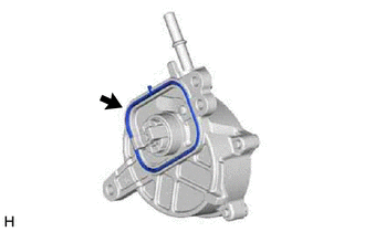
Install a new No. 1 vacuum pump O-ring to the vacuum pump assembly.
-
-
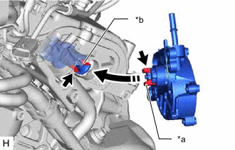
*a Coupling Teeth *b Groove Install the vacuum pump assembly so that the coupling teeth of the vacuum pump assembly and groove of the camshaft are engaged.
Note
-
Ensure that the vacuum pump assembly is installed securely.
-
Be careful not to pinch the No. 1 vacuum pump O-ring.
-
-
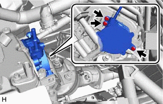
Using an 8 mm socket wrench, install the vacuum pump assembly with the 3 bolts.
- Torque:
- 10 N*m { 102 kgf*cm, 7 ft.*lbf }
Note
After installation, check that there are no gaps between the matching surfaces and that the vacuum pump assembly is not installed at an angle.
-
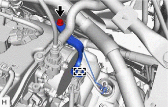
Align the connector with the vacuum pump assembly, and push them together until the connector makes a "click" sound.
Note
-
Check that there is no foreign matter on the connecting parts.
-
After connecting the connector, check that the vacuum pump assembly and connector are securely connected by pulling on them.
-
-
-
INSTALL WIRING HARNESS CLAMP BRACKET
-
install the wiring harness clamp bracket with the bolt.
- Torque:
- 12 N*m { 122 kgf*cm, 9 ft.*lbf }
-
Engage the clamp.
-
-
INSTALL NO. 1 WATER BY-PASS TUBE
-
CONNECT OUTLET HEATER WATER HOSE
-
CONNECT INLET HEATER WATER HOSE
-
CONNECT ENGINE WIRE HARNESS
-
INSTALL NO. 1 VACUUM SWITCHING VALVE ASSEMBLY
-
INSTALL V-BANK COVER BRACKET
-
CONNECT FUEL VAPOR FEED PIPE
-
INSTALL THROTTLE W/MOTOR BODY ASSEMBLY
-
ADD COOLANT (for Intercooler)
-
INSPECT FOR COOLANT LEAK (for Intercooler)
-
INSTALL FENDER APRON BRACE SUB-ASSEMBLY RH
-
INSTALL CENTER NO. 2 COWL TOP VENTILATOR LOUVER
-
INSTALL HOOD TO COWL TOP SEAL
-
INSTALL RADIATOR COVER PLATE
-
INSTALL V-BANK COVER SUB-ASSEMBLY
-
INSPECT VACUUM PUMP OPERATION