FRONT SEAT OUTER BELT ASSEMBLY INSTALLATION

CAUTION / NOTICE / HINT
Tech Tips
-
Use the same procedure for RHD and LHD vehicles.
-
The procedure listed below is for LHD vehicles.
-
Use the same procedure for the RH and LH sides.
-
The procedure listed below is for the LH side.
-
A bolt without a torque specification is shown in the standard bolt chart.
PROCEDURE
-
INSTALL FRONT SHOULDER BELT ANCHOR ADJUSTER ASSEMBLY
-
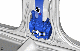
Connect the guide and temporarily install the front shoulder belt anchor adjuster assembly with the 2 bolts.
-
Tighten the bolts in the order shown in the illustration to install the front shoulder belt anchor adjuster assembly LH.
- Torque:
- 42 N*m { 428 kgf*cm, 31 ft.*lbf }
-
-
INSTALL FRONT SHOULDER BELT ANCHOR PLATE SUB-ASSEMBLY LH
-
Attach the 6 guides to install the front shoulder belt anchor plate sub-assembly LH.
-
-
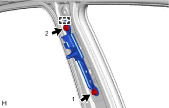
INSTALL FRONT SEAT OUTER BELT ASSEMBLY LH
-
Attach the 2 guides and install the front seat outer belt assembly with the bolt.
- Torque:
- 12.5 N*m { 127 kgf*cm, 9 ft.*lbf }
-
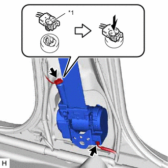
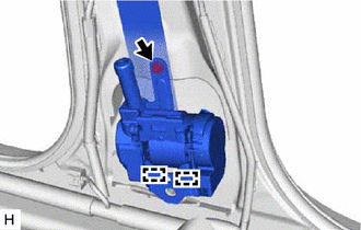
*1 Locking Button Connect the pretensioner connector and lock the locking button as shown in the illustration.
Note
Securely lock the locking button.
-
Connect the connector.
-
Connect the shoulder anchor of the front seat outer belt assembly LH with the nut.
- Torque:
- 42 N*m { 428 kgf*cm, 31 ft.*lbf }
-
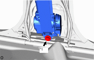
*1 Bolt A Connect the floor anchor of the front seat outer belt assembly LH with the bolt A.
- Torque:
- 42 N*m { 428 kgf*cm, 31 ft.*lbf }
-
Check that the ELR locks.
Note
The check should be performed with the front seat outer belt assembly installed.
-
With the belt assembly installed, check that the belt locks when it is pulled out quickly.
-
-
*1 Bolt A Remove the bolt A and disconnect the floor anchor of the front seat outer belt assembly LH.
-
-
INSTALL FRONT SEAT OUTER BELT ASSEMBLY RH (for Front Passenger Seat Belt with Selectable Force Limiter)
-
Align the 2 claws with the seat belt positioning holes, and install the retractor of the front seat outer belt assembly RH with the bolt as shown in the illustration.
- Torque:
- 12.5 N*m { 127 kgf*cm, 9 ft.*lbf }
-
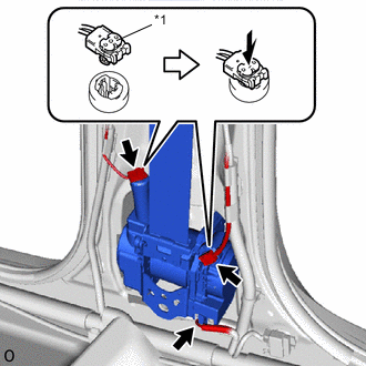
*1 Locking Button Connect the pretensioner connector and selectable force limiter connector, and lock the 2 locking buttons as shown in the illustration.
Note
Securely lock the locking button.
-
Connect the connector.
-
Connect the shoulder anchor of the front seat outer belt assembly with the nut.
- Torque:
- 42 N*m { 428 kgf*cm, 31 ft.*lbf }
-
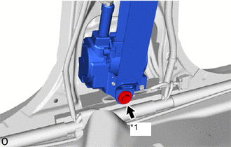
*1 Bolt A Connect the floor anchor of the front seat outer belt assembly RH with the bolt A.
- Torque:
- 42 N*m { 428 kgf*cm, 31 ft.*lbf }
-
Check that the ELR locks.
Note
The check should be performed with the front seat outer belt assembly installed.
-
With the belt assembly installed, check that the belt locks when it is pulled out quickly.
-
-
*1 Bolt A Remove the bolt A and disconnect the floor anchor of the front seat outer belt assembly RH.
-
-
INSTALL CENTER PILLER GARNISH ASSEMBLY LH
-
INSTALL LOWER CENTER PILLAR GARNISH LH
-
INSTALL FRONT DOOR OPENING TRIM WEATHERSTRIP LH
-
INSTALL REAR DOOR OPENING TRIM WEATHERSTRIP LH
-
CONNECT FRONT SEAT OUTER BELT ASSEMBLY LH
-
Connect the floor anchor of the front seat outer belt assembly LH with the bolt.
- Torque:
- 42 N*m { 428 kgf*cm, 31 ft.*lbf }
-
-
INSTALL LAP BELT OUTER ANCHOR COVER
-
Attach the guide, 2 claws and install the lap belt anchor cover.
-
-
INSTALL REAR DOOR SCUFF PLATE LH
-
INSTALL DOOR SCUFF PLATE ASSEMBLY LH
-
CONNECT CABLE TO NEGATIVE BATTERY TERMINAL
Note
When disconnecting the cable, some systems need to be initialized after the cable is reconnected.
-
CHECK SRS WARNING LIGHT