WATER PUMP INSTALLATION

CAUTION / NOTICE / HINT
Note
This procedure includes the installation of small-head bolts. Refer to Small-Head Bolts of Basic Repair Hint to identify the small-head bolts.
Tech Tips
-
Use the same procedure for RHD and LHD vehicles.
-
The procedure listed below is for LHD vehicles.
PROCEDURE
-
INSTALL ENGINE WATER PUMP ASSEMBLY
-
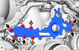

Bolt A 
Bolt B 
Bolt C Temporarily install a new water pump gasket with the 9 bolts.
Note
-
Make sure that there is no oil on the threads of the bolts A and B.
-
Do not reuse the water pump gasket.
Standard Length Item Length Bolt A 80 mm (3.15 in.) Bolt B 55 mm (2.17 in.) Bolt C 14 mm (0.551 in.) -
-
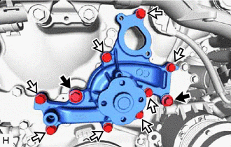
Bolt A Bolt B Temporarily install the engine water pump assembly with the 10 bolts.
Note
Make sure that there is no oil on the threads of the bolts A.
Standard Length Item Length Bolt A 90 mm (3.54 in.) Bolt B 25 mm (0.984 in.) -
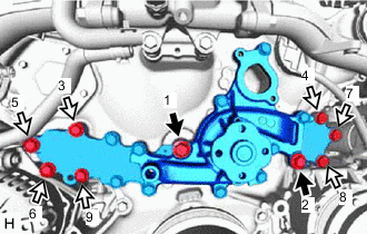
Bolt A Bolt B Tighten the 9 bolts in the order shown in the illustration.
- Torque:
- for bolt A
- 43 N*m { 438 kgf*cm, 32 ft.*lbf }
- for bolt B
- 21 N*m { 214 kgf*cm, 15 ft.*lbf }
-
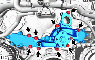
Tighten the 10 bolts to install the water pump gasket and engine water pump assembly.
- Torque:
- 21 N*m { 214 kgf*cm, 15 ft.*lbf }
-
-
INSTALL CYLINDER BLOCK WATER DRAIN COCK SUB-ASSEMBLY
-
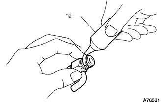
*a Adhesive Apply adhesive to 2 or 3 threads of the cylinder block water drain cock sub-assembly.
Adhesive Toyota Genuine Adhesive 1344, Three Bond 1344 or equivalent Note
-
After applying adhesive 1344, install the cylinder block water drain cock sub-assembly within 3 minutes.
-
Do not pour in coolant within 1.0 hours of installing the cylinder block water drain cock sub-assembly and leave the sub-assembly as it is.
-
-
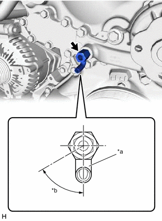
*a Pipe *b 60° Install the cylinder block water drain cock sub-assembly to the engine water pump assembly as shown in the illustration.
- Torque:
- 25 N*m { 255 kgf*cm, 18 ft.*lbf }
Tech Tips
-
After tightening to the specified torque, if the pipe of the cylinder block water drain cock sub-assembly does not come within the range shown in the illustration, retighten it again and set it to the range shown in the illustration.
-
Make sure the tightening angle is within 360°. (Upper torque limit: 45 N*m (459 kgf*cm))
-
Do not loosen after tightening.
-
-
INSTALL CYLINDER BLOCK WATER DRAIN COCK PLUG
-
Install the cylinder block water drain cock plug to the cylinder block water drain cock sub-assembly.
- Torque:
- 12.7 N*m { 130 kgf*cm, 9 ft.*lbf }
-
-
INSTALL WATER INLET ASSEMBLY
-
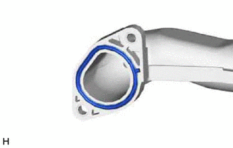
Install a new water inlet pipe gasket to the water inlet assembly.
-
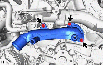
Install the water inlet assembly with the 3 bolts.
- Torque:
- 10 N*m { 102 kgf*cm, 7 ft.*lbf }
-
-
INSTALL ENGINE COOLANT TEMPERATURE SENSOR
-
CONNECT NO. 2 WATER BY-PASS PIPE SUB-ASSEMBLY
-
Install the 2 bolts to connect the No. 2 water by-pass pipe sub-assembly.
- Torque:
- 10 N*m { 102 kgf*cm, 7 ft.*lbf }
-
Connect the No. 2 water by-pass hose and No. 5 water by-pass hose to the No. 2 water by-pass pipe sub-assembly, and slide the clip to secure the hose.
Note
Align the direction of the claw on the clip with the paint mark on the hose.
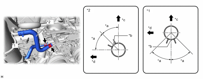
*1 No. 2 Water By-pass Hose *2 No. 5 Water By-pass Hose *a 45° *b Paint Mark *c Upper Side *d Front Side -
Connect the No. 4 water by-pass hose and No. 6 water by-pass hose to the No. 2 water by-pass pipe sub-assembly and throttle body with motor assembly, and slide the clip to secure the hose.
Note
Align the direction of the claw on the clip with the paint mark on the hose.
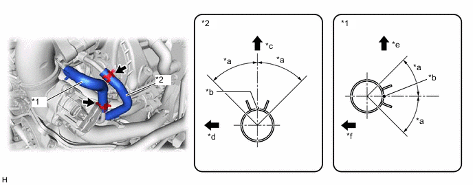
*1 No. 4 Water By-pass Hose *2 No. 6 Water By-pass Hose *a 45° *b Paint Mark *c Upper Side *d Front Side *e Rear Side *f RH Side
-
-
INSTALL V-RIBBED BELT TENSIONER ASSEMBLY
-
Install the v-ribbed belt tensioner assembly with the 2 bolts.
- Torque:
- 21 N*m { 214 kgf*cm, 15 ft.*lbf }
-
-
INSTALL IDLER PULLEY SUB-ASSEMBLY
-
Install the idler pulley sub-assembly with the bolt.
- Torque:
- 43 N*m { 438 kgf*cm, 32 ft.*lbf }
-
-
INSTALL WATER PUMP PULLEY
-
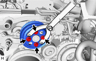
Temporarily install the water pump pulley with the 4 bolts.
-
Using SST, hold the water pump pulley.
- SST
- 09960-10010 ( 09962-01000, 09963-00500 )
-
Tighten the 4 bolts.
- Torque:
- 21 N*m { 214 kgf*cm, 15 ft.*lbf }
-
-
INSTALL FAN AND GENERATOR V BELT
-
CONNECT WATER HOSE
-
Connect the water hose to the water inlet assembly, and slide the clip to secure the hose.
Note
-
Install so that the water hose paint mark and water inlet assembly positioning stopper are securely overlapped.
-
Make sure the water hose is securely inserted to the stopper. (Axial Direction)
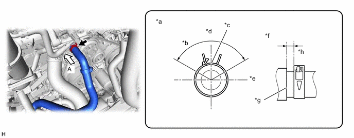
*a View A *b 120° *c Paint Mark *d Upper Side *e LH Side *f Axis Direction *g Stopper *h 2 to 7 mm (0.0787 to 0.276 in.) -
-
-
CONNECT NO. 4 RADIATOR HOSE
-
Connect the No. 4 radiator hose to the water inlet assembly, and slide the clip to secure the hose.
Note
Install so that the No. 4 radiator hose paint mark and water inlet assembly positioning stopper are securely overlapped. (Rotational Direction)
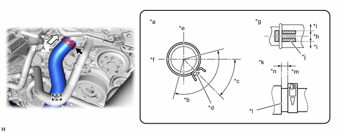
*a View A *b 120° *c 45.4° *d Paint Mark *e Upper Side *f RH Side *g Rotational Direction *h OK *i NG *j Variation Range *k Axis Direction *l Stopper *m 2 to 6 mm (0.0787 to 0.236 in.) *n 0 to 1 mm (0 to 0.0394 in.)
-
-
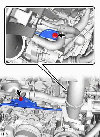
INSTALL NO. 1 TURBO PRESSURE SENSOR (for Bank 2)
-
INSTALL WATER CONTROL VALVE
-
INSTALL NO. 1 WATER BY-PASS TUBE
-
INSTALL INTERCOOLER RESERVE TANK ASSEMBLY
-
INSTALL RADIATOR RESERVE TANK ASSEMBLY
-
INSTALL AIR CLEANER ASSEMBLY LH
-
INSTALL AIR CLEANER ASSEMBLY RH
-
INSTALL RADIATOR SUPPORT TO CROSSMEMBER BRACE SUB-ASSEMBLY LH
-
INSTALL RADIATOR SUPPORT TO CROSSMEMBER BRACE SUB-ASSEMBLY RH
-
ADD ENGINE COOLANT
-
ADD COOLANT (for Intercooler)
-
INSPECT FOR COOLANT LEAK
-
INSPECT FOR COOLANT LEAK (for Intercooler)
-
INSTALL LOWER RADIATOR AIR DEFLECTOR
-
INSTALL UPPER RADIATOR SUPPORT SEAL
-
INSTALL RADIATOR COVER PLATE
-
INSTALL V-BANK COVER SUB-ASSEMBLY
-
INSTALL STRUT BAR BRACKET SUPPORT SUB-ASSEMBLY (for AWD)
-
INSTALL FRONT SUSPENSION MEMBER BRACE (for AWD)
-
INSTALL OIL PAN PROTECTOR (for 2WD)
-
INSTALL NO. 1 ENGINE UNDER COVER ASSEMBLY
-
for 2WD:
-
for AWD:
-