ROOF HEADLINING REMOVAL

CAUTION / NOTICE / HINT
The necessary procedures (adjustment, calibration, initialization or registration) that must be performed after parts are removed, installed or replaced during the roof headlining assembly removal/installation are shown below.
| Replacement Part or Procedure | Necessary Procedures | Effects / Inoperative when not Performed | Link |
|---|---|---|---|
| Disconnect cable from negative (-) battery terminal | Drive the vehicle until stop and start control is permitted (approximately 5 to 60 minutes) | Stop and start system | |
| Memorize steering angle neutral point | LKA/LDA system | ||
| Parking support brake system* | |||
| Pre-collision system | |||
| Adaptive high beam system | |||
Lighting system (EXT) |
|||
| Variable gear ratio steering system | |||
| Parking assist monitor system | |||
| Panoramic view monitor system | |||
| Initialize rear door sunshade system | Rear door sunshade system | ||
| Initialize power trunk lid system | Power trunk lid system |
Click here Click here
Tech Tips
-
Use the same procedure for RHD and LHD vehicles.
-
The procedure listed below is for LHD vehicles.
PROCEDURE
-
REMOVE FRONT SEAT ASSEMBLY LH
-
REMOVE FRONT SEAT ASSEMBLY RH
Tech Tips
Use the same procedure described for the LH side.
-
REMOVE REAR SEAT CUSHION ASSEMBLY (for Fixed Seat Type)
-
REMOVE NO. 1 SEAT ARMREST CAP (for Fixed Seat Type)
-
REMOVE REAR SEATBACK ASSEMBLY (for Fixed Seat Type)
-
REMOVE REAR SEAT CUSHION LOCK HOOK (for Fixed Seat Type)
-
REMOVE REAR SEATBACK HOLDER (for Fixed Seat Type)
-
REMOVE REAR SEAT CUSHION ASSEMBLY LH (for Power Seat)
-
REMOVE REAR SEAT CUSHION ASSEMBLY RH (for Power Seat)
Tech Tips
Use the same procedure described for the LH side.
-
REMOVE REAR SEAT CUSHION LOCK HOOK (for Power Seat)
-
REMOVE REAR SEATBACK ASSEMBLY LH (for Power Seat)
-
REMOVE REAR SEATBACK ASSEMBLY RH (for Power Seat)
Tech Tips
Use the same procedure described for the LH side.
-
REMOVE FRONT DOOR SCUFF PLATE LH
-

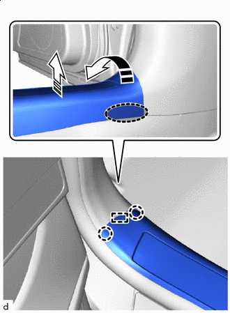
Protective Tape Apply protective tape around the front door scuff plate LH.
-

Place hand here 
Remove in this Direction (1) 
Remove in this Direction (2) Place your hand at the position shown in the illustration and pull in the removal direction (1) to detach the claw.
-
Lift in the removal direction (2) to detach the clamp and claw.
-
Place hands here Remove in this Direction Place both hands at the position shown in the illustration and lift in the direction indicated by the arrow to detach the clamp and claw and remove the front door scuff plate LH.
-
-
REMOVE FRONT DOOR SCUFF PLATE RH
Tech Tips
Use the same procedure described for the LH side.
-
REMOVE REAR DOOR SCUFF PLATE LH
-
Protective Tape Apply protective tape around the rear door scuff plate LH.
-
Place hand here Remove in this Direction (1) Remove in this Direction (2) Place your hand at the position shown in the illustration and pull in the removal direction (1) to detach the claw.
-
Lift in the removal direction (2) to detach the clamp and claw.
-
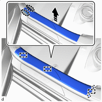
Place hands here Remove in this Direction Place both hands at the position shown in the illustration and lift in the direction indicated by the arrow to detach the clamp and claw and remove the rear door scuff plate LH.
-
-
REMOVE REAR DOOR SCUFF PLATE RH
Tech Tips
Use the same procedure described for the LH side.
-
REMOVE FRONT PILLAR GARNISH LH
-
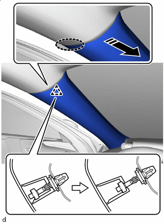
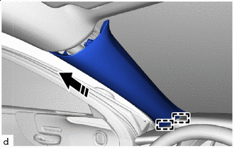
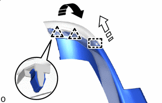
Place hand here Remove in this Direction Place your hand at the position shown in the illustration and pull in the direction indicated by the arrow to detach the front pillar garnish clip and slightly pull the upper part of the front pillar garnish LH away from the vehicle.
-
*a Release Lever 
Push Push in the release lever with your fingers and detach the front pillar garnish clip from the vehicle.
Note
If there is extreme damage to the front pillar garnish clip, replace it with a new one.
-
When the front pillar garnish clip cannot be detached by pressing the knobs with the fingers:
-
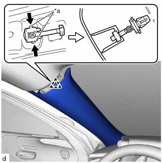
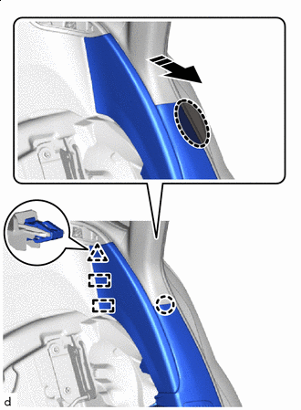
Direction (A) Push Lift up the front pillar garnish clip in the direction (A) while pressing the portion indicated by the arrow in the illustration with your fingers.
-
Direction (B) Release Lever 
Push Push in the portion indicated by the arrow in the illustration with the screwdriver end while pulling the front pillar garnish clip with your fingers in the direction (B) to detach the front pillar garnish clip.
Note
If there is extreme damage to the front pillar garnish clip, replace it with a new one.
-
-
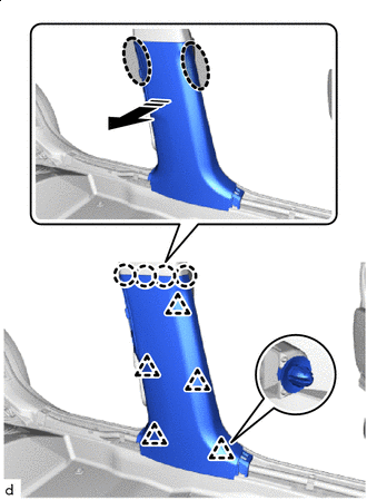
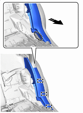
Place hand here Remove in this Direction Place your hand in the gap and pull in the direction indicated by the arrow to detach the front pillar garnish clip and lift the bottom part of the front pillar garnish LH.
-
*a Release Lever Push Push in the release lever with your fingers and detach the front pillar garnish clip from the vehicle.
Note
If there is extreme damage to the front pillar garnish clip, replace it with a new one.
-
When the front pillar garnish clip cannot be detached by pressing the knobs with the fingers:
-

Direction (A) Push Lift up the front pillar garnish clip in the direction (A) while pressing the portion indicated by the arrow in the illustration with your fingers.
-

Direction (B) Release Lever Push Push in the portion indicated by the arrow in the illustration with the screwdriver end while pulling the front pillar garnish clip with your fingers in the direction (B) to detach the front pillar garnish clip.
Note
If there is extreme damage to the front pillar garnish clip, replace it with a new one.
-
-
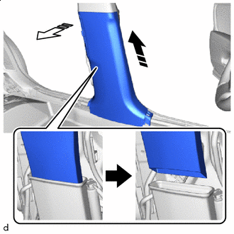
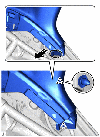
Remove in this Direction Pull the front pillar garnish LH in the direction indicated by the arrow shown in the illustration to detach the guide and remove the front pillar garnish LH.
-
Protect the curtain shield airbag assembly.
-
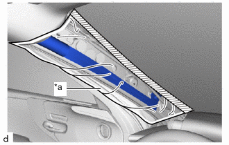
*a Protective Cover Adhesive Tape Cover the airbag with a cloth or piece of nylon and secure both ends of the cover with adhesive tape as shown in the illustration.
Note
Cover the curtain shield airbag assembly with a protective cover as soon as the front pillar garnish LH is removed.
-
-
-
REMOVE FRONT PILLAR GARNISH RH
Tech Tips
Use the same procedure described for the LH side.
-
REMOVE LOWER CENTER PILLAR GARNISH LH
-
Place hands here Remove in this Direction Place both hands at the position shown in the illustration and pull in the direction indicated by the arrow shown in the illustration to detach the claw and clip.
-
Remove in this Direction (1) Remove in this Direction (2) Lift in the removal direction (1) shown in the illustration to pull out the rear cooler air duct adapter LH.
-
Remove the lower center pillar garnish LH in the removal direction (2) shown in the illustration.
-
-
REMOVE LOWER CENTER PILLAR GARNISH RH
Tech Tips
Use the same procedure described for the LH side.
-
REMOVE UPPER CENTER PILLAR GARNISH LH
-
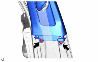
Remove the 2 clips.
-
Place hands here Remove in this Direction Place both hands at the position shown in the illustration, detach the clip and hook and remove the upper center pillar garnish LH.
-
-
REMOVE UPPER CENTER PILLAR GARNISH RH
Tech Tips
Use the same procedure described for the LH side.
-
REMOVE REAR SEAT SIDE GARNISH LH
-
for Fixed Seat Type:
-
Place hand here Remove in this Direction Place your hand at the position shown in the illustration and pull in the direction indicated by the arrow to detach the clamp and claw.
-
Place hand here Remove in this Direction Place your hand at the position shown in the illustration and pull in the direction indicated by the arrow to detach the clip and claw and remove the rear seat side garnish LH.
-
Remove in this Direction (1) Remove in this Direction (2) Pull in the removal direction (1) shown in the illustration to detach the clip.
-
Pull in the removal direction (2) shown in the illustration to detach the guide and remove the seat belt guide from the rear seat side garnish LH.
-
-
for Power Seat:
-
Place hand here Remove in this Direction Place your hand at the position shown in the illustration and pull in the direction indicated by the arrow to detach the clamp.
-
Place hand here Remove in this Direction Place your hand at the position shown in the illustration and pull in the direction indicated by the arrow to detach the claw, clip and guide and remove the rear seat side garnish LH.
-
-
-
REMOVE REAR SEAT SIDE GARNISH RH
Tech Tips
Use the same procedure described for the LH side.
-
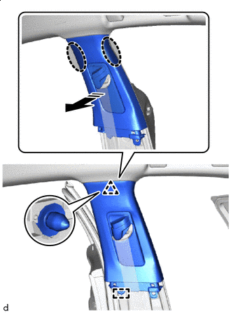
REMOVE ROOF SIDE RAIL GARNISH ASSEMBLY LH
-
Place hand here Remove in this Direction Place your hand at the position shown in the illustration and pull in the direction indicated by the arrow to detach the clip.
-
Place hand here Remove in this Direction Place your hand at the position shown in the illustration and pull in the direction indicated by the arrow to detach the clip.
-
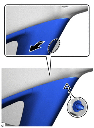
Place hand here Remove in this Direction Place your hand in the gap and pull in the direction indicated by the arrow to detach the clip.
-
Remove in this Direction Pull in the direction indicated by the arrow to detach the clip and remove the roof side rail garnish LH.
-
-
REMOVE ROOF SIDE RAIL GARNISH ASSEMBLY RH
Tech Tips
Use the same procedure described for the LH side.
-
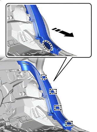
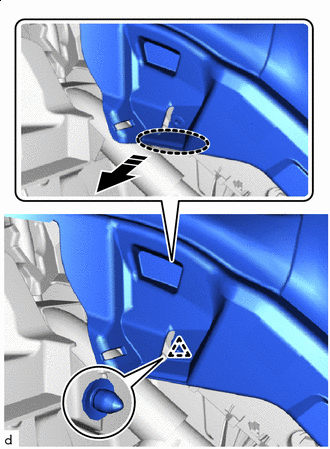
REMOVE PACKAGE TRAY TRIM GARNISH LH
-
Protective Tape Apply protective tape at the position shown in the illustration.
-
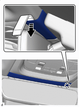
Remove in this Direction Using moulding remover D, detach the clip.
-
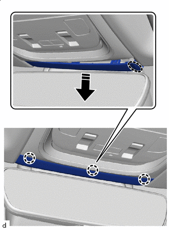
Remove in this Direction Pull in the direction indicated by the arrow to detach the guide and remove the package tray trim garnish LH.
-
-
REMOVE PACKAGE TRAY TRIM GARNISH RH
Tech Tips
Use the same procedure described for the LH side.
-
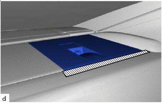
REMOVE PACKAGE TRAY TRIM SIDE COVER LH
-
*1 Inner Roof Side Garnish Assembly LH Place hand here Remove in this Direction Place your hand at the position shown in the illustration and pull in the direction indicated by the arrow to detach the clip and clamp and remove the package tray trim side cover LH.
Note
When detaching clamp A, push down on the roof side inner garnish assembly LH side.
-
-
REMOVE PACKAGE TRAY TRIM SIDE COVER RH
Tech Tips
Use the same procedure described for the LH side.
-
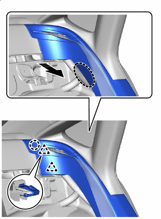
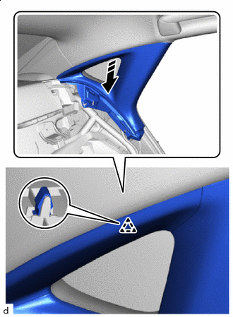
REMOVE INNER ROOF SIDE GARNISH ASSEMBLY LH
-

Place hand here Remove in this Direction Place your hand at the position shown in the illustration and detach the clip.
-
Remove in this Direction Detach the guide and remove the inner roof side garnish assembly LH in the direction indicated by the arrow shown in the illustration.
-
-
REMOVE INNER ROOF SIDE GARNISH ASSEMBLY RH
Tech Tips
Use the same procedure described for the LH side.
-
REMOVE ASSIST GRIP SUB-ASSEMBLY
Tech Tips
Use the same procedure for all assist grip assemblies.
-
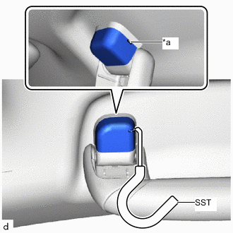
*a Cutout Insert SST into the cutout of the assist grip cover LH as shown in the illustration.
- SST
- 09813-00010
Note
To prevent the assist grip assembly from being damaged, make sure to insert SST straight into the cutout.
-
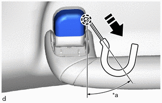
*a 30 to 45° Remove in this Direction Pull SST as shown in the illustration to disengage the claw.
Note
To prevent the assist grip assembly from being damaged, make sure to only pull SST as shown in the illustration.
Tech Tips
Use the same procedure for the claw on the other side of the assist grip cover LH.
-
Remove the assist grip cover LH.
Tech Tips
Use the same procedure for the LH side and RH side.
-
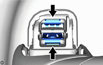
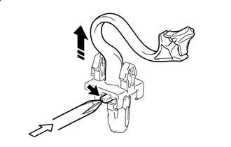
Pinch the clip with needle-nose pliers.
Tech Tips
Use the same procedure for both clips.
-
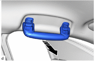
Remove in this Direction Hold the handle and pull in the direction indicated by the arrow shown in the illustration to remove the assist grip sub-assembly.
-
Using needle-nose pliers, remove the clip.
-
-
REMOVE COAT HOOK (w/ Rear Cooler)
Tech Tips
Use the same procedure for the opposite side.
-
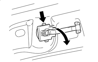
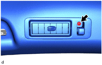
Remove the screw.
-
Remove in this Direction Pull in the direction indicated by the arrow shown in the illustration to detach the claw and remove the coat hook.
-
-
REMOVE SPOT LIGHT ASSEMBLY
-
REMOVE VANITY MIRROR ASSEMBLY
-
REMOVE VISOR BRACKET COVER LH
-
Detach the claw and remove the visor bracket cover LH.
-
-
REMOVE VISOR ASSEMBLY LH
-
Remove the 2 screws.
-
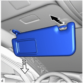
Remove in this Direction (1) Remove in this Direction (2) Pull in the removal direction (1) shown in the illustration to detach the visor assembly RH from the visor holder LH.
-
Pull in the removal direction (2) shown in the illustration to detach the visor assembly LH.
Note
Do not twist or remove it in any direction other than down, since doing so may damage the connector.
-
-
REMOVE VISOR HOLDER LH
-
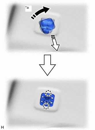
*a 45° Remove in this Direction (1) Remove in this Direction (2) Turn the visor holder LH end approximately 45° in the direction (1) indicated by the arrow and pull it out in the direction (2) indicated by the arrow shown in the illustration.
-
Detach the claw and remove the visor holder LH.
-
-
REMOVE VISOR BRACKET COVER RH
Tech Tips
Use the same procedure described for the LH side.
-
REMOVE VISOR ASSEMBLY RH
Tech Tips
Use the same procedure described for the LH side.
-
REMOVE VISOR HOLDER RH
Tech Tips
Use the same procedure described for the LH side.
-
REMOVE VANITY LIGHT ASSEMBLY
-
REMOVE FRONT ROOF TOP GARNISH
-
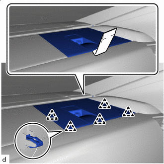
Remove in this Direction Insert moulding remover D at the position shown in the illustration and pull in the direction indicated by the arrow to detach the claw.
-
Place hand here Remove in this Direction Place your hand in the gap and detach the claw.
-
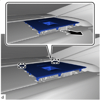
Remove in this Direction Pull in the direction indicated by the arrow shown in the illustration to detach the guide and remove the front roof top garnish.
-
-
REMOVE MAP LIGHT ASSEMBLY
-
REMOVE WINDSHIELD GLASS
-
REMOVE ROOF HEADLINING ASSEMBLY
-
Rear pillar RH side:
-
Disconnect the 3 connectors.
-
-
Front pillar LH side:
-
Remove the protective cover installed to the front pillar LH.
-
Using a clip remover, detach the clamp.
-
Disconnect the 3 connectors.
-
Install the protective cover to the front pillar LH.
-
-
Disconnect the connector.
-
w/ Rear Cooler:
-
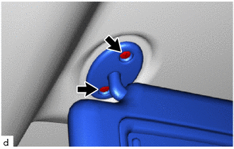
Remove the screw.
Tech Tips
Use the same procedure for the opposite side.
-
-
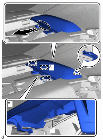
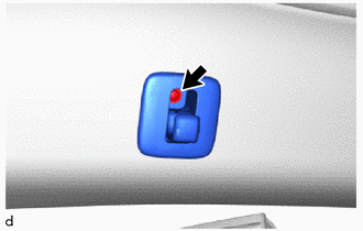
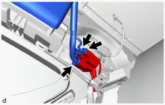
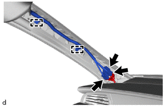
Place your hand at the position shown in the illustration and pull in the direction indicated by the arrow to detach the hook, fastener and claw.
-
Detach the guide.
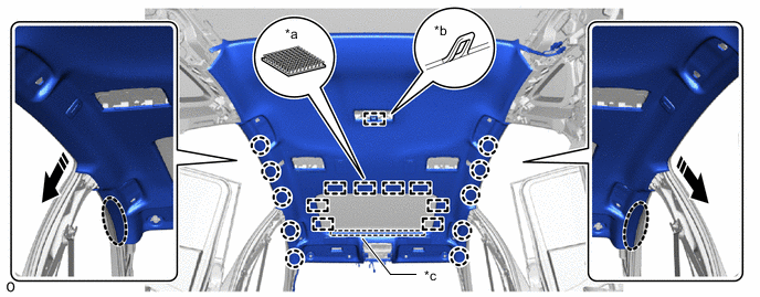
*a Fastener *b Hook *c Guide - - Place hand here Remove in this Direction Note
-
When removing the roof headlining assembly, always detach the claws one side at a time.
-
Have 1 or 2 people support the roof headlining assembly on the side with the detached claws while detaching the claws on the other side.
-
-
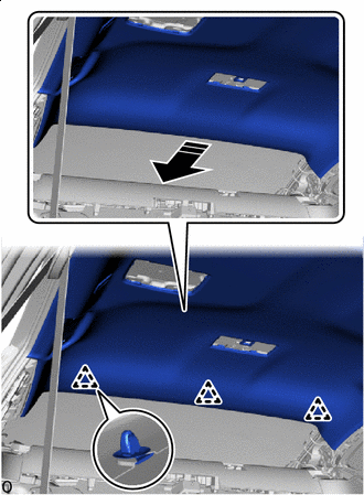
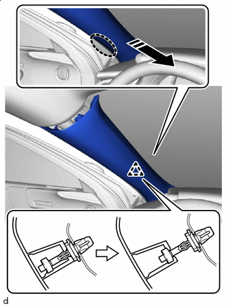
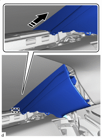
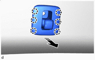
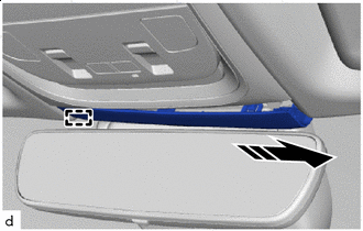
Remove in this Direction Slide the roof headlining assembly toward the rear of the vehicle and detach the clip.
Tech Tips
The 3 clips remain on the vehicle side.
-
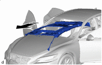
Remove in this Direction Tilt the roof headlining assembly and carry it out of the front of the vehicle.
Note
-
Make sure wrinkles do not form in the roof headlining assembly during removal.
-
Make sure the roof headlining does not get caught, as it may bend or get damaged.
-
Do not damage the roof headlining or body interior.
-
-
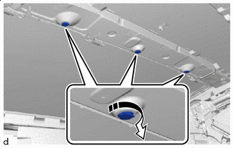
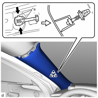
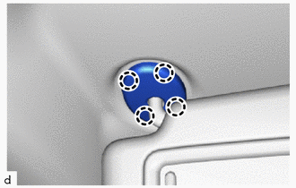
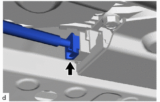
Remove in this Direction Turn in the direction indicated by the arrow shown in the illustration and remove the 3 clips from the vehicle.
-
Remove the grommet from the vehicle.
Tech Tips
Use the same procedure for the opposite side.
-
-
REMOVE OUTSIDE FRONT DOOR SCUFF PLATE LH
-
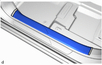
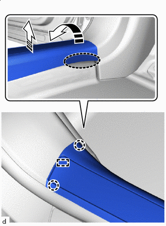
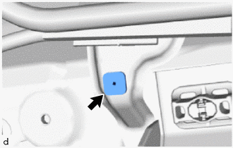
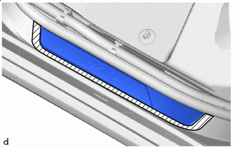
Protective Tape Apply protective tape around the outside front door scuff plate LH.
-
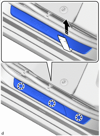
Remove in this Direction Insert moulding remover D at the position shown in the illustration and lift in the direction indicated by the arrow to detach the claw and outside front door scuff plate LH.
-
-
REMOVE OUTSIDE FRONT DOOR SCUFF PLATE RH
Tech Tips
Use the same procedure described for the LH side.
-
REMOVE OUTSIDE REAR DOOR SCUFF PLATE LH
-
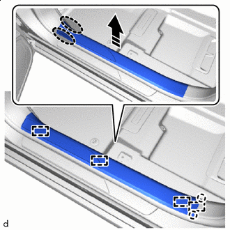
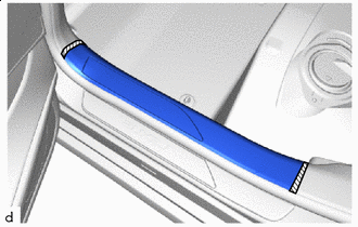
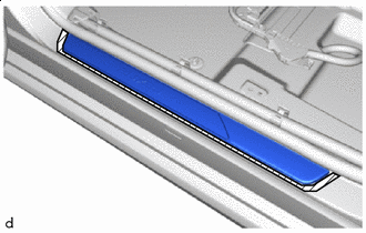
Protective Tape Apply protective tape around the outside rear door scuff plate LH.
-
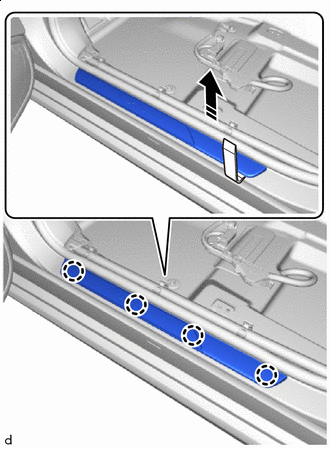
Remove in this Direction Insert moulding remover D at the position shown in the illustration and lift in the direction indicated by the arrow to detach the claw and outside rear door scuff plate LH.
-
-
REMOVE OUTSIDE REAR DOOR SCUFF PLATE RH
Tech Tips
Use the same procedure described for the LH side.