SFI SYSTEM (w/o Secondary Air Injection System), Diagnostic DTC:P2119
| DTC Code | DTC Name |
|---|---|
| P2119 | Throttle Actuator Control Throttle Body Range / Performance |
DESCRIPTION
The Electronic Throttle Control System (ETCS) is composed of the throttle actuator, throttle position sensor, accelerator pedal position sensor and ECM. The ECM operates the throttle actuator to regulate the throttle valve in response to driver inputs. The throttle position sensor detects the opening angle of the throttle valve and provides the ECM with feedback so that the throttle valve can be appropriately controlled by the ECM.
| DTC No. | DTC Detection Condition | Trouble Area |
|---|---|---|
| P2119 | Throttle valve opening angle continues to vary greatly from the target opening angle (1 trip detection logic). |
|
MONITOR DESCRIPTION
The ECM determines the actual opening angle of the throttle valve from the throttle position sensor signal. The actual opening angle is compared to the target opening angle calculated by the ECM. If the difference between these two values is outside the standard range, the ECM interprets this as a malfunction in the ETCS. The ECM then illuminates the MIL and stores the DTC.
If the malfunction is not repaired successfully, the DTC is stored when the accelerator pedal is quickly released (to close the throttle valve) after the engine speed reaches 5000 rpm by the accelerator pedal being fully depressed (fully opening the throttle valve).
FAIL-SAFE
When this DTC or other DTCs relating to ETCS (Electronic Throttle Control System) malfunctions are stored, the ECM enters fail-safe mode. During fail-safe mode, the ECM cuts the current to the throttle actuator and the throttle valve is returned to a 6.5° throttle angle by the return spring. The ECM then adjusts the engine output by controlling the fuel injection (intermittent fuel-cut) and ignition timing in accordance with the accelerator pedal position to allow the vehicle to continue at a minimal speed. If the accelerator pedal is depressed firmly and gently, the vehicle can be driven slowly.
The ECM continues operating in fail-safe mode until a pass condition is detected, and the ignition switch is then turned off.
WIRING DIAGRAM
Refer to DTC P2102 Click here.
INSPECTION PROCEDURE
Tech Tips
Read freeze frame data using the intelligent tester. Freeze frame data records the engine condition when malfunctions are detected. When troubleshooting, freeze frame data can help determine if the vehicle was moving or stationary, if the engine was warmed up or not, if the air-fuel ratio was lean or rich, and other data from the time the malfunction occurred.
PROCEDURE
-
CHECK FOR ANY OTHER DTCS OUTPUT (IN ADDITION TO DTC P2119)
-
Connect the intelligent tester to the DLC3.
-
Turn the ignition switch to ON.
-
Turn the intelligent tester on.
-
Enter the following menus: Powertrain / Engine and ECT / DTC.
-
Read the DTCs.
Result Result Proceed to P2119 is output A P2119 and other DTCs are output B Tech Tips
If any DTCs other than P2119 are output, troubleshoot those DTCs first.
B 
GO TO DTC CHART Click here
A 
-
-
READ VALUE USING INTELLIGENT TESTER (THROTTLE POSITION)
-
Connect the intelligent tester to the DLC3.
-
Turn the ignition switch to ON.
-
Turn the intelligent tester on.
-
Clear the DTCs Click here.
-
Turn the ignition switch off and wait for at least 30 seconds.
-
Turn the ignition switch to ON.
-
Enter the following menus: Powertrain / Engine and ECT / Data List / Throttle Position No. 1 and Throttle Position Command.
-
Check the values displayed on the intelligent tester while fully depressing and releasing the accelerator pedal quickly.
Result Result Proceed to Throttle Position No. 1 does not change A Throttle Position No. 1 changes even a little B Tech Tips
When a DTC is output, the system changes to fail-safe mode. Therefore, only use the data up until the time the DTC is stored for confirmation.
B 
INSPECT THROTTLE BODY ASSEMBLY (VISUALLY CHECK THROTTLE VALVE) Click here
A
-
-
INSPECT THROTTLE BODY ASSEMBLY (RESISTANCE OF THROTTLE ACTUATOR)
-
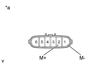
Text in Illustration *a Component without harness connected
(Throttle Body Assembly)
Disconnect the throttle body assembly connector.
-
Measure the resistance according to the value(s) in the table below.
Standard Resistance Tester Connection Condition Specified Condition 2 (M+) - 1 (M-) 20°C (68°F) 0.3 to 100 Ω
NG
REPLACE THROTTLE BODY ASSEMBLY Click here
OK
-
-
INSPECT THROTTLE BODY ASSEMBLY (VISUALLY CHECK THROTTLE VALVE)
-
Check for contamination between the throttle valve and housing. If necessary, clean the throttle body. Also, check that the throttle valve moves smoothly.
OK Throttle valve is not contaminated with foreign objects and moves smoothly.
NG
REPLACE THROTTLE BODY ASSEMBLY Click here
OK
-
-
READ VALUE USING INTELLIGENT TESTER (THROTTLE POSITION)
-
Connect the intelligent tester to the DLC3.
-
Turn the ignition switch to ON.
-
Turn the intelligent tester on.
-
Clear the DTCs Click here.
-
Turn the ignition switch off and wait for at least 30 seconds.
-
Turn the ignition switch to ON.
-
Enter the following menus: Powertrain / Engine and ECT / Data List / Throttle Position No. 1, Throttle Position No. 2 and Throttle Position Command.
-
Check the values displayed on the intelligent tester while wiggling the ECM wire harness.
-
Enter the following menus: Powertrain / Engine and ECT / DTC.
-
Check for DTCs.
Result Result Proceed to Value in Data List changes when wire harness is wiggled, or DTC is output A Other than above B
B
CHECK WHETHER DTC OUTPUT RECURS (DTC P2119) Click here
A
-
-
REPAIR OR REPLACE HARNESS OR CONNECTOR (ECM - THROTTLE BODY ASSEMBLY)
-
As the DTC was stored due to a change in the contact resistance of the connector, repair or replace the wire harness or connector Click here.
NEXT 
END
-
-
REPLACE THROTTLE BODY ASSEMBLY
-
Replace the throttle body assembly Click here.
NEXT
-
-
CHECK WHETHER DTC OUTPUT RECURS (DTC P2119)
-
Connect the intelligent tester to the DLC3.
-
Turn the ignition switch to ON.
-
Turn the intelligent tester on.
-
Clear the DTCs Click here.
-
Turn the ignition switch off and wait for at least 30 seconds.
-
Start the engine.
-
Allow the engine to idle for 20 seconds or more.
-
Fully depress and release the accelerator pedal several times quickly.
-
Enter the following menus: Powertrain / Engine and ECT / DTC.
-
Read the DTCs.
Result Result Proceed to No DTC is output A P2119 is output B
B
REPLACE ECM Click here
A
END
-