HEADLIGHT ASSEMBLY(for Triple Beam Headlight) REMOVAL
CAUTION / NOTICE / HINT
The necessary procedures (adjustment, calibration, initialization or registration) that must be performed after parts are removed and installed, or replaced during headlight assembly removal/installation are shown below.
| Replaced Part or Performed Procedure | Necessary Procedure | Effect/Inoperative Function when Necessary Procedure not Performed | Link |
|---|---|---|---|
| Front bumper assembly | Front television camera view adjustment | Panoramic view monitor system | Click here for Initialization Click here for Calibration |
| Front bumper assembly (w/ Intelligent clearance sonar system) |
|
|
|
| Headlight ECU sub-assembly LH |
|
|
Note
If the headlight assembly RH is replaced with a new one, vehicle information registration and initialization are not necessary.
Tech Tips
-
Use the same procedure for the RH side and LH side.
-
The following procedure is for the LH side.
PROCEDURE
-
REMOVE FRONT BUMPER ASSEMBLY
-
DISCONNECT FRONT FENDER REINFORCEMENT SUB-ASSEMBLY TOP
-
Remove the center hood cushion and clip.
-
Disengage the 2 claws and 2 guides to disconnect the front fender reinforcement sub-assembly top.
-
-
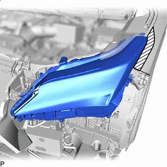
REMOVE HEADLIGHT ASSEMBLY
-

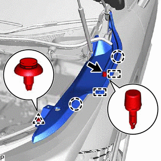
Protective Tape Apply protective tape around the headlight assembly as shown in the illustration.
-
*a Connector Lock Lever 
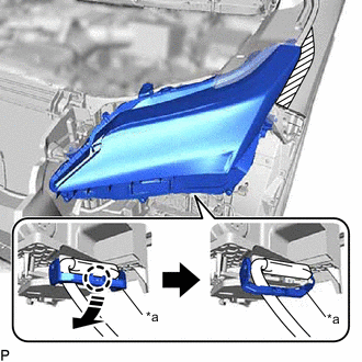
Disconnect in this Direction Disengage the claw, pull down the connector lock lever as shown in the illustration and disconnect the connector.
-
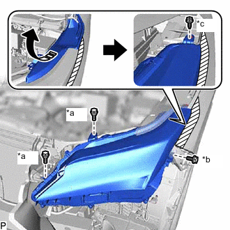
*a Bolt <A> *b Bolt <B> *c Screw Pull Back in this Direction Remove the 2 bolts <A> and bolt <B>.
-
Pull back the front fender reinforcement sub-assembly top and remove the screw as shown in the illustration.
-
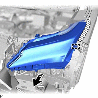
Remove in this Direction Disengage the guide to remove the headlight assembly as shown in the illustration.
-