POP UP HOOD LIFTER(for Rear Side) INSTALLATION

CAUTION / NOTICE / HINT
Tech Tips
-
Use the same procedure for the RH and LH sides.
-
The procedure listed below is for the LH side.
PROCEDURE
-
INSTALL NO. 2 POP UP HOOD LIFTER ASSEMBLY
-
Check that the engine switch is off.
-
Check that the cable is disconnected from the negative (-) battery terminal.
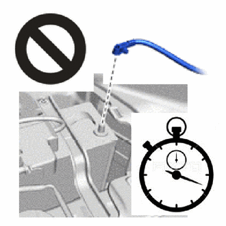
CAUTION:
-
Wait at least 90 seconds after disconnecting the cable from the negative (-) battery terminal to disable the SRS system.
-
If the airbag deploys for any reason, it may cause a serious accident.
-
-
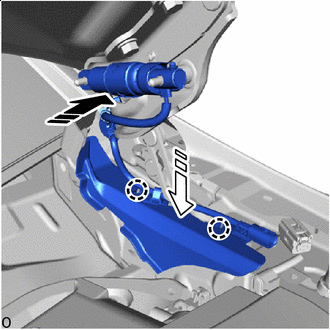

Install No. 2 Pop Up Hood Lifter Assembly LH in this Direction 
Install Pop Up Hood Cover in this Direction Attach the claw to install the pop up hood cover.
-
Set the No. 2 pop up hood lifter assembly LH in place.
-
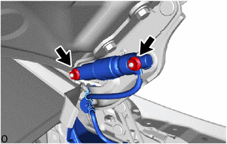
Install 2 new nuts.
- Torque:
- 11.5 N*m { 117 kgf*cm, 8 ft.*lbf }
-
Attach the wire harness clamp.
-
Connect the pop up hood lifter connector.
-
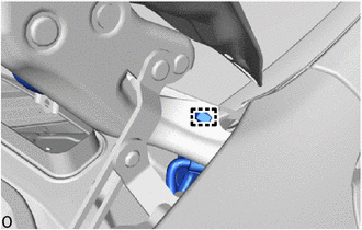
Before connecting the connector, check that the position of the housing lock is correct as shown in the illustration.
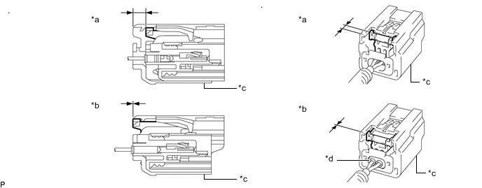
*a Correct *b Incorrect *c CPA *d Housing -
*a Housing Lock *b CPA *c CPA Upper Part Connect in this Direction While holding the CPA be sure to engage the connectors until they are locked and check that the CPA is in its original position (when locking, make sure that a click sound can be heard).
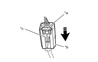
Note
Do not push down the upper part of the CPA shown in the illustration when connecting the pop up hood lifter connector.
-
-
-
INSTALL COWL TOP VENTILATOR LOUVER SUB-ASSEMBLY
-
INSTALL CENTER COWL TOP VENTILATOR LOUVER
-
INSTALL CENTER NO. 2 COWL TOP VENTILATOR LOUVER
-
INSTALL COWL TOP VENTILATOR LOUVER REINFORCEMENT
-
INSTALL HOOD TO COWL TOP SEAL
-
INSTALL FRONT WIPER ARM AND BLADE ASSEMBLY LH
-
INSTALL FRONT WIPER ARM AND BLADE ASSEMBLY RH
-
INSTALL FRONT WIPER ARM HEAD CAP
-
INSTALL FRONT FENDER REINFORCEMENT SUB-ASSEMBLY TOP LH
-
INSTALL RADIATOR COVER PLATE
-
INSTALL UPPER RADIATOR SUPPORT SEAL
-
CONNECT CABLE TO NEGATIVE BATTERY TERMINAL
for 8GR-FKS:
for V35A-FTS:
Note
When disconnecting the cable, some systems need to be initialized after the cable is reconnected.
-
INSTALL LUGGAGE COMPARTMENT MAT SUB-ASSEMBLY
-
PERFORM DIAGNOSTIC SYSTEM CHECK
-
CHECK SRS WARNING LIGHT