WIPER AND WASHER SYSTEM Washer Fluid Level Warning Switch Circuit
DESCRIPTION
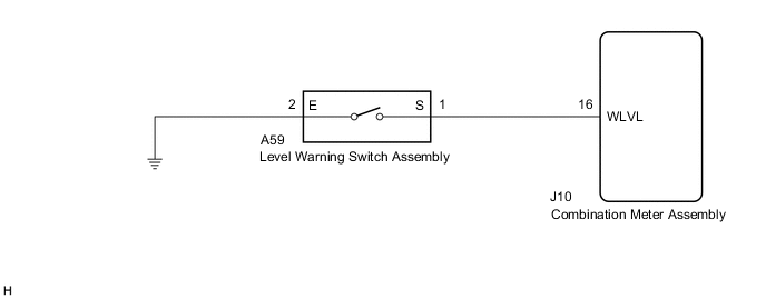
When the washer fluid level is lower than a certain level, a warning message is displayed on the combination meter assembly.
WIRING DIAGRAM
CAUTION / NOTICE / HINT
Note
Inspect the fuses of circuits related to this system before performing the following procedure.
PROCEDURE
-
READ VALUE USING GTS
-
Connect the GTS to the DLC3.
-
Turn the engine switch on (IG).
-
Turn the GTS on.
-
Enter the following menus: Body Electrical / Combination Meter / Data List.
-
Read the Data List according to the display on the GTS.
Body Electrical > Combination Meter > Data ListTester Display Measurement Item Range Normal Condition Diagnostic Note Washer Switch Washer fluid level warning switch ON or OFF ON: Washer fluid level low
OFF: Washer fluid level not low
-
Body Electrical > Combination Meter > Data ListTester Display Washer Switch OK The GTS display changes correctly in response to the washer fluid level. Result Proceed to OK NG
OK 
GO TO METER / GAUGE SYSTEM Click here
NG 
-
-
CHECK HARNESS AND CONNECTOR (LEVEL WARNING SWITCH ASSEMBLY - COMBINATION METER ASSEMBLY)
-
Disconnect the A59 level warning switch assembly connector.
-
Measure the voltage according to the value(s) in the table below.
Standard Voltage Tester Connection Condition Specified Condition A59-1 (S) - Body ground Engine switch off Below 1 V A59-1 (S) - Body ground Engine switch on (IG) 11 to 14 V Result Proceed to OK NG
NG 
CHECK HARNESS AND CONNECTOR (WASHER MOTOR AND PUMP ASSEMBLY - WINDSHIELD WIPER SWITCH ASSEMBLY) Click here
OK
-
-
CHECK HARNESS AND CONNECTOR (LEVEL WARNING SWITCH ASSEMBLY - BODY GROUND)
-
Measure the resistance according to the value(s) in the table below.
Standard Resistance Tester Connection Condition Specified Condition A59-2 (E) - Body ground Always Below 1 Ω Result Proceed to OK NG
OK
REPLACE LEVEL WARNING SWITCH ASSEMBLY Click here
NG
REPAIR OR REPLACE HARNESS OR CONNECTOR
-
-
CHECK HARNESS AND CONNECTOR (WASHER MOTOR AND PUMP ASSEMBLY - WINDSHIELD WIPER SWITCH ASSEMBLY)
-
Disconnect the J10 combination meter assembly connector.
-
Measure the resistance according to the value(s) in the table below.
Standard Resistance Tester Connection Condition Specified Condition A59-1 (S) - J10-16 (WLVL) Always Below 1 Ω A59-1 (S) or J10-16 (WLVL) - Body ground Always 10 kΩ or higher Result Proceed to OK NG
OK
REPLACE COMBINATION METER ASSEMBLY Click here
NG
REPAIR OR REPLACE HARNESS OR CONNECTOR
-