OIL LEVEL SENSOR REMOVAL
CAUTION / NOTICE / HINT
The necessary procedures (adjustment, calibration, initialization or registration) that must be performed after parts are removed and installed, or replaced during engine oil level sensor removal/installation are shown below.
| Replaced Part or Performed Procedure | Necessary Procedure | Effect/Inoperative Function when Necessary Procedure not Performed | Link |
|---|---|---|---|
| Battery terminal is disconnected/reconnected | Memorize steering angle neutral point | LKA /LDA system | |
| Pre-crash safety system | |||
| Lighting system (EXT)
|
|||
| Adaptive high beam system | |||
| Drive the vehicle until stop and start control is permitted (approximately 15 to 60 minutes) | Stop and start system | ||
| Memorize steering angle neutral point | Parking Assist Monitor System (w/ Parallel Parking Assist Function) | ||
| Parking Assist Monitor System (w/o Parallel Parking Assist Function) | |||
| Panoramic view monitor system | |||
| Initialize back door lock | Power door lock control system | ||
| Reset back door close position | Power back door system | ||
| Replacement of ECM | Perform Vehicle Identification Number (VIN) or frame number registration |
|
Click here for 2GR-FKS (w/ Canister Pump Module) Click here for 2GR-FKS (w/o Canister Pump Module) |
| ECU Communication ID Registration (Immobiliser system) | Engine start function | See Service Bulletin for the registration method. | |
| Gas leaks from exhaust system | Inspection After Repair |
|
Click here for 2GR-FKS (w/ Canister Pump Module) Click here for 2GR-FKS (w/o Canister Pump Module) |
w/ Canister Pump Module |
Inspection After Repair |
|
|
w/o Canister Pump Module |
Inspection After Repair |
|
|
| Replacement of automatic transaxle assembly | Perform the following procedures in the order shown:
|
|
for Initialization: Click here for Registration: Click here for Initialization: Click here for Registration: Click here |
| Replacement of ECM (If possible, read the transaxle compensation code from the previous ECM) |
Perform the following procedures in the order shown:
|
||
| Replacement of ECM (If impossible, read the transaxle compensation code from the previous ECM) |
Perform the following procedures in the order shown:
|
||
| Front wheel alignment adjustment |
|
|
|
| Suspension, tires, etc. (The vehicle height changes because of suspension or tire replacement) |
Rear television camera assembly optical axis (Back camera position setting) | Parking assist monitor system (w/ Parallel Parking Assist Function) | for Initialization: Click here for Calibration: Click here |
| Parking assist monitor system (w/o Parallel Parking Assist Function) | for Initialization: Click here for Calibration: Click here |
||
|
Panoramic view monitor system | for Initialization: Click here for Calibration: Click here |
|
| Initialize headlight ECU sub-assembly LH |
|
PROCEDURE
-
INSTALL ENGINE ASSEMBLY TO ENGINE STAND
-
REMOVE NO. 2 OIL PAN SUB-ASSEMBLY
-
REMOVE OIL STRAINER SUB-ASSEMBLY
-
REMOVE ENGINE OIL LEVEL SENSOR
-
Disconnect the engine oil level sensor connector.
-
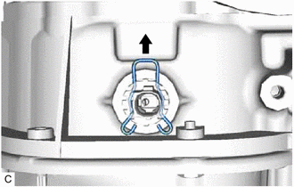
Remove the clip from the engine oil level sensor.
-
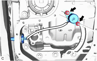
Remove the 2 bolts and engine oil level sensor.
-