REAR DIFFERENTIAL CARRIER ASSEMBLY REMOVAL

CAUTION / NOTICE / HINT
The necessary procedures (adjustment, calibration, initialization, or registration) that must be performed after parts are removed and installed, or replaced during rear differential carrier assembly with differential support removal/installation are shown below.
| Replaced Part or Performed Procedure | Necessary Procedure | Effect/Inoperative Function when Necessary Procedure not Performed | Link |
|---|---|---|---|
| Rear wheel alignment adjustment |
|
|
|
| Suspension, tires, etc. (The vehicle height changes because of suspension or tire replacement) |
Rear television camera assembly optical axis (Back camera position setting) | Parking assist monitor system (w/ Parallel Parking Assist Function) | for Initialization: Click here for Calibration: Click here |
| Rear television camera assembly optical axis (Back camera position setting) | Parking assist monitor system (w/o Parallel Parking Assist Function) | for Initialization: Click here for Calibration: Click here |
|
|
Panoramic view monitor system | for Initialization: Click here for Calibration: Click here |
|
| Initialize headlight ECU sub-assembly LH |
|
||
|
|
||
| Gas leaks from exhaust system | Inspection after repair |
|
for 8AR-FTS (for Rear Air Fuel Ratio Sensor): Click here for 8AR-FTS (for Rear Heated Oxygen Sensor): Click here for 2GR-FKS (w/ Canister Pump Module): Click here for 2GR-FKS (w/o Canister Pump Module): Click here |
CAUTION:
The rear differential carrier assembly with differential support is very heavy. Be sure to follow the procedure described in the repair manual, or the engine lifter may suddenly drop.
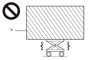
| *a | Object Exceeding Weight Limit of Engine Lifter |
PROCEDURE
-
DRAIN DIFFERENTIAL OIL
-
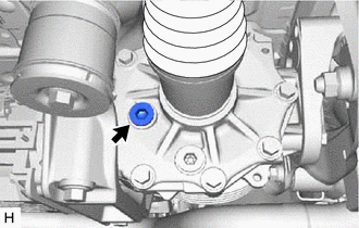
Using a 10 mm hexagon wrench, remove the differential inspection plug and gasket.
-
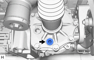
Using a 10 mm hexagon wrench, remove the rear differential drain plug and gasket to drain the differential oil.
-
-
REMOVE PROPELLER WITH CENTER BEARING SHAFT ASSEMBLY
-
REMOVE REAR DRIVE SHAFT ASSEMBLY
-
Remove the rear drive shaft assembly LH and RH.
-
-
REMOVE REAR STABILIZER BAR
w/o Rear No. 2 Seat: Click here
w/ Rear No. 2 Seat: Click here
-
LOOSEN NO. 2 REAR DIFFERENTIAL SUPPORT
Tech Tips
Loosen the bolts only when removal of the No. 2 rear differential support is required.
-
Loosen the 2 bolts.
-
-
REMOVE REAR DIFFERENTIAL CARRIER ASSEMBLY WITH DIFFERENTIAL SUPPORT
Note
-
Do not damage the contact surface when removing the rear differential carrier assembly with differential support.
-
The remaining oil may leak out when removing the rear differential carrier assembly with differential support.
-
Securely support the rear differential carrier assembly with differential support while performing this step to avoid excessively tilting or dropping the rear differential carrier assembly with differential support.
-
Remove the bolts and nuts with the rear differential carrier assembly with differential support secured.
-
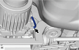
Disconnect the vacuum hose from the electro magnetic control coupling sub-assembly.
-
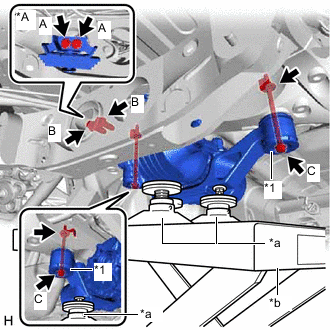
*A 8AR-FTS *1 Lower Rear Differential Mount Stopper *a Attachment *b Engine Lifter Support the rear differential carrier assembly with differential support with an engine lifter using 3 attachments or equivalent tools as shown in the illustration.
-
for 8AR-FTS:
-
Remove the 2 bolts (A) and rear differential dynamic damper from the differential support.
-
-
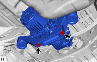
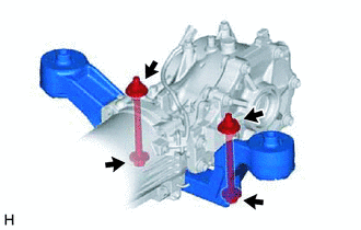
for 2GR-FKS:
-
Remove the 2 bolts (B).
-
-
Remove the 2 bolts (C), 2 nuts and 2 lower rear differential mount stoppers from the No. 2 rear differential support.
Tech Tips
The nuts have tabs to prevent them from rotating.
-
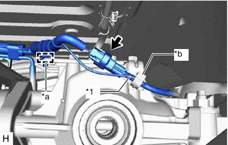
*1 Vacuum Hose *a Clamp (A) *b Clamp (B) Disconnect the connector and disengage the clamp (A).
-
Separate the vacuum hose from the clamp (B).
-
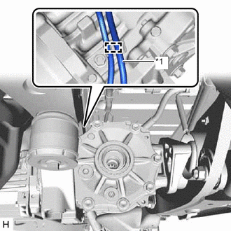
*1 Vacuum Hose Slightly lower the rear differential carrier assembly with differential support, remove the vacuum hose from the clamp.
Note
Do not damage the vacuum hose and electro magnetic control coupling wire harness.
Tech Tips
Lower the engine lifter to the extent that the vacuum hose can still be removed.
-
Lower the rear differential carrier assembly with differential support slowly to remove the rear differential carrier assembly with differential support.
Note
-
Do not damage the vacuum hose and electro magnetic control coupling wire harness.
-
Move the engine lifter forward and backward as necessary to prevent the rear differential carrier assembly with differential support from contacting the rear suspension member sub-assembly.
-
-
-
REMOVE DIFFERENTIAL SUPPORT
-
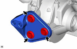
Remove the 3 bolts and differential support from the rear differential carrier assembly.
-
-
REMOVE UPPER REAR DIFFERENTIAL MOUNT STOPPER
-
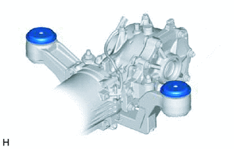
Remove the 2 upper rear differential mount stoppers from the No. 2 rear differential support.
-
-
REMOVE NO. 2 REAR DIFFERENTIAL SUPPORT
-
Remove the 2 bolts, 2 nuts and No. 2 rear differential support.
Tech Tips
The nuts have tabs to prevent them from rotating.
-