REAR COMBINATION LIGHT ASSEMBLY(w/o Rear No. 2 Seat) REMOVAL
CAUTION / NOTICE / HINT
The necessary procedures (adjustment, calibration, initialization or registration) that must be performed after parts are removed and installed, or replaced during rear combination light assembly removal/installation are shown below.
| Replaced Part or Performed Procedure | Necessary Procedure | Effect/Inoperative Function when Necessary Procedure not Performed | Link |
|---|---|---|---|
| Disconnect cable from negative battery terminal | Memorize steering angle neutral point | LKA/LDA System | |
| Intelligent clearance sonar system*1 | |||
| Pre-crash safety system | |||
| Lighting System (EXT)
|
|||
| Adaptive high beam system | |||
| Drive the vehicle until stop and start control is permitted (approximately 15 to 60 minutes) | Stop and start system | ||
| Memorize steering angle neutral point | Parking assist monitor system (w/ Parallel parking assist function) | ||
| Parking assist monitor system (w/o Parallel parking assist function) | |||
| Panoramic view monitor system | |||
| Initialize back door lock | Power door lock control system | ||
| Reset back door close position | Power back door system |
*1: When performing learning using the GTS.
CAUTION:
Some of these service operations affect the SRS airbag system. Read the precautionary notices concerning the SRS airbag system before servicing.
Tech Tips
-
Use the same procedure for the RH side and LH side.
-
The following procedure is for the LH side.
PROCEDURE
-
REMOVE TONNEAU COVER ASSEMBLY
-
REMOVE DECK BOARD ASSEMBLY
-
REMOVE REAR NO. 3 FLOOR BOARD
-
REMOVE SPARE WHEEL COVER (for Compact Spare Tire)
-
REMOVE REAR DECK FLOOR BOX (w/ Spare Tire)
-
REMOVE REAR FLOOR CARPET (w/o Spare Tire)
-
REMOVE REAR NO. 4 FLOOR BOARD (except Full Size Spare Tire)
-
REMOVE REAR NO. 4 FLOOR BOARD (for Full Size Spare Tire)
-
REMOVE FRONT DECK FLOOR BOX (w/ Spare Tire)
for LH Side:
-
REMOVE DECK FLOOR BOX RH (w/o Spare Tire)
-
REMOVE DECK FLOOR BOX LH (w/o Spare Tire)
for LH Side:
-
REMOVE DECK SIDE TRIM BOX RH (except Full Size Spare Tire)
-
REMOVE DECK SIDE TRIM BOX RH (for Full Size Spare Tire)
-
REMOVE REAR FLOOR FINISH PLATE
-
REMOVE REAR DOOR SCUFF PLATE LH
-
REMOVE REAR SEAT ASSEMBLY LH (for LH Side)
-
REMOVE REAR SEAT ASSEMBLY RH (for RH Side)
-
REMOVE UPPER QUARTER TRIM PAD LH
-
REMOVE REAR SEAT SIDE GARNISH LH
-
REMOVE REAR FLOOR FINISH SIDE PLATE LH
-
REMOVE NO. 1 LUGGAGE COMPARTMENT TRIM HOOK (for LH Side)
-
REMOVE NO. 1 LUGGAGE COMPARTMENT TRIM HOOK (for RH Side)
-
REMOVE ROPE HOOK ASSEMBLY
-
REMOVE NO. 1 LUGGAGE COMPARTMENT LIGHT ASSEMBLY (for LH Side)
-
REMOVE NO. 1 LUGGAGE COMPARTMENT LIGHT ASSEMBLY (for RH Side)
-
REMOVE DECK TRIM SIDE PANEL ASSEMBLY LH (for LH Side)
-
REMOVE RECLINING REMOTE CONTROL BEZEL RH (w/o Rear Power Seat System)
for RH Side:
-
REMOVE FOLD SEAT SWITCH ASSEMBLY (w/ Rear Power Seat System)
for RH Side:
-
REMOVE DECK TRIM SIDE PANEL ASSEMBLY RH (for RH Side)
-
REMOVE REAR LIGHT COVER
-
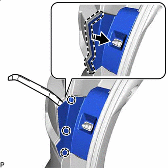

Insert Moulding Remover Here 
Remove in this Direction Using a moulding remover, disengage the 3 claws as shown in the illustration.
-
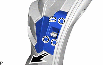
Remove in this Direction Disengage the 3 claws and guide to remove the rear light cover as shown in the illustration.
-
-
REMOVE REAR COMBINATION LIGHT ASSEMBLY
-
Disconnect the connector.
-
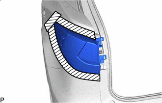

Protective Tape Apply protective tape around the rear combination light assembly as shown in the illustration.
-
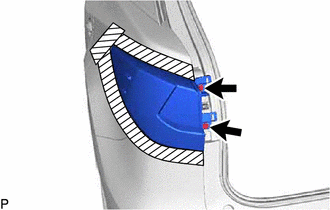
Remove the 2 screws.
-
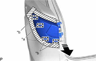
*a Pin *b Guide Remove in this Direction Pull the rear combination light assembly toward the rear of the vehicle as shown in the illustration to disengage the pin and 3 guides and separate the rear combination light assembly.
Note
To prevent the rear combination light assembly from falling when disengaging the pin, lightly hold the rear combination light assembly.
-
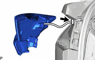
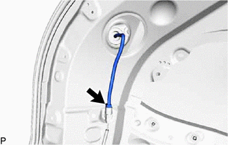
Disengage the grommet to remove the rear combination light assembly.
-