DIFFERENTIAL MOUNT CUSHION REPLACEMENT

CAUTION / NOTICE / HINT
The necessary procedures (adjustment, calibration, initialization, or registration) that must be performed after parts are removed and installed, or replaced during rear No. 2 differential mount cushion replacement are shown below.
| Replaced Part or Performed Procedure | Necessary Procedure | Effect/Inoperative Function when Necessary Procedure not Performed | Link |
|---|---|---|---|
| Rear wheel alignment adjustment |
|
|
|
| Suspension, tires, etc. (The vehicle height changes because of suspension or tire replacement) |
Rear television camera assembly optical axis (Back camera position setting) | Parking assist monitor system (w/ Parallel Parking Assist Function) | for Initialization: Click here for Calibration: Click here |
| Rear television camera assembly optical axis (Back camera position setting) | Parking assist monitor system (w/o Parallel Parking Assist Function) | for Initialization: Click here for Calibration: Click here |
|
|
Panoramic view monitor system | for Initialization: Click here for Calibration: Click here |
|
| Initialize headlight ECU sub-assembly LH |
|
||
| Gas leaks from exhaust system | Inspection after repair |
|
for 8AR-FTS: Click here for 2GR-FKS (w/ Canister Pump Module): Click here for 2GR-FKS (w/o Canister Pump Module): Click here |
PROCEDURE
-
REMOVE REAR DIFFERENTIAL CARRIER ASSEMBLY WITH DIFFERENTIAL SUPPORT
-
REMOVE REAR NO. 2 DIFFERENTIAL MOUNT CUSHION
-
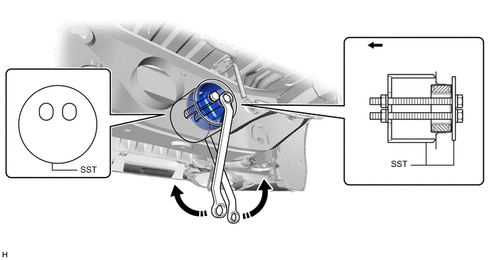
Using SST, remove the rear No. 2 differential mount cushion.
- SST
- 09570-48010

Rear of the Vehicle - - Note
-
Before using SST, apply grease to the SST bolts.
-
Be sure to use the correct combination of SST.
-
Be sure to use the correct direction of SST.
-
Make sure that SST contacts the entire circumference of the rear No. 2 differential mount cushion.
-
Do not tilt the bolts of SST.
-
Tighten the 2 bolts of SST so that they enter the 2 holes of the rear No. 2 differential mount cushion by an equal amount.
-
-
INSTALL REAR NO. 2 DIFFERENTIAL MOUNT CUSHION
-
Using SST, install a new rear No. 2 differential mount cushion.
- SST
- 09570-48010
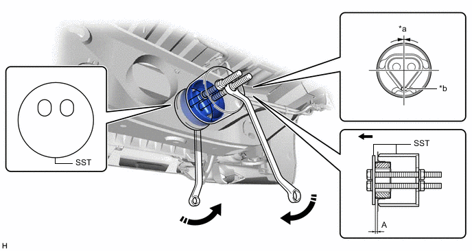
*a 0° +/- 3° *b Protrusion Rear of the Vehicle - - Standard Distance (A) 9.8 to 10.8 mm (0.386 to 0.425 in.) Note
-
Make sure that the rear No. 2 differential mount cushion is aligned within 3° from the center.
-
Install the rear No. 2 differential mount cushion so that the protrusion is positioned as shown in the illustration.
-
Temporarily install the rear No. 2 differential mount cushion to the rear suspension member sub-assembly in order to prevent it from tilting, and then install SST.
-
Before using SST, apply grease to the SST bolt.
-
Be sure to use the correct combination of SST.
-
Be sure to use the correct direction of SST.
-
Make sure that SST contacts the entire circumference of the rear No. 2 differential mount cushion.
-
Do not tilt the bolts of SST.
-
Tighten the 2 bolts of SST so that they enter the 2 holes of the rear No. 2 differential mount cushion by an equal amount.
-
-
TEMPORARILY INSTALL REAR DIFFERENTIAL CARRIER ASSEMBLY WITH DIFFERENTIAL SUPPORT