AUTOMATIC TRANSMISSION SYSTEM, Diagnostic DTC:P2719, P2720, P2721

| DTC Code | DTC Name |
|---|---|
| P2719 | Pressure Control Solenoid "D" Circuit Performance (SLT Solenoid) |
| P2720 | Pressure Control Solenoid "D" Control Circuit Low |
| P2721 | Pressure Control Solenoid "D" Control Circuit High |
DESCRIPTION
The shift solenoid valve SLT is controlled by the duty ratio as determined in advance by the transmission control computer, based upon signals from the accelerator position sensor, input speed sensor NT and output speed sensor SP2. In this way, the line pressure is adjusted to match the throttle valve opening angle and engine output. The TCM uses the revolution signals from the input speed sensor NT and output speed sensor SP2 to detect clutch and other slipping.
| DTC No. | DTC Detection Condition
|
Trouble Area |
|---|---|---|
| P2719 |
|
|
| P2720 |
|
|
| P2721 |
|
|
MONITOR DESCRIPTION
When an open or short in the shift solenoid valve SLT circuit or feedback stuck is detected, the TCM interprets this as a fault. The TCM will turn on the MIL and store the DTC.
WIRING DIAGRAM
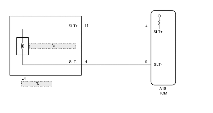
| *a | Shift Solenoid Valve SLT |
| *b | Transmission Wire |
CAUTION / NOTICE / HINT
Note
Perform the universal trip to clear permanent DTCs Click here.
PROCEDURE
-
CHECK HARNESS AND CONNECTOR
-
Disconnect the A18 TCM connector.
-
Measure the resistance according to the value(s) in the table below.
Standard resistance Tester Connection Condition Specified Condition A18-4(SLT+) - A18-9(SLT-) 20°C(68°F) 5.0 to 5.6 Ω -
Disconnect the A18 TCM connector.
NG 
CHECK HARNESS AND CONNECTOR (TRANSMISSION WIRE - TCM) Click here
OK 
-
-
REPLACE TCM
-
Replace the TCM Click here.
NEXT 
PERFORM THE RESET MEMORY Click here
-
-
CHECK HARNESS AND CONNECTOR (TRANSMISSION WIRE - TCM)
-
Disconnect the A18 TCM connector.
-
Disconnect the L4 transmission wire connector.
-
Measure the resistance according to the value(s) in the table below.
Standard resistance Tester Connection Condition Specified Condition A18-4(SLT+) - L4-11(SLT+) Always Below 1 Ω A18-9(SLT-) - L4-4(SLT-) Always Below 1 Ω -
Measure the voltage according to the value(s) in the table below.
Standard voltage Tester Connection Condition Specified Condition A18-4(SLT+) - Body ground Ignition switch ON Below 1 V A18-9(SLT-) - Body ground Ignition switch ON Below 1 V -
Connect the A18 TCM connector.
-
Connect the L4 transmission wire connector.
NG
REPAIR OR REPLACE HARNESS OR CONNECTOR
OK
-
-
INSPECT SHIFT SOLENOID VALVE SLT
-
Remove the shift solenoid valve SLT Click here.
-
Perform inspection of the shift solenoid valve SLT Click here.
OK
REPAIR OR REPLACE TRANSMISSION WIRE Click here
NG
REPLACE SHIFT SOLENOID VALVE SLT Click here
-