FRONT PNEUMATIC CYLINDER(for 2WD) INSTALLATION
CAUTION / NOTICE / HINT
Tech Tips
-
Use the same procedure for the RH and LH side.
-
The following procedure is for the LH side.
PROCEDURE
-
TEMPORARILY TIGHTEN FRONT PNEUMATIC CYLINDER WITH SHOCK ABSORBER ASSEMBLY LH
-
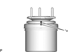
*a Paintmark When installing a new front pneumatic cylinder with shock absorber assembly LH:
-
Align the paintmarks on the front suspension support assembly and pneumatic cylinder chamber.
-
-
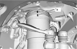
*a Matchmark When reusing the front pneumatic cylinder with shock absorber assembly LH:
-
Install 2 new O-rings, a new plate and new No. 2 connector to the front pneumatic cylinder with shock absorber assembly LH.
-
Align the matchmarks on the front suspension support assembly and pneumatic cylinder chamber.
-
-
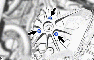
Temporarily tighten the front pneumatic cylinder with shock absorber assembly LH (upper side) with the 3 nuts.
-
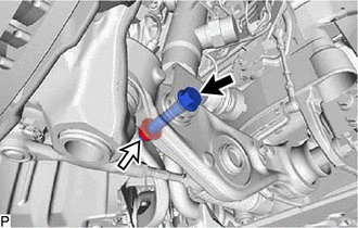

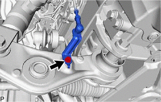
Bolt 
Nut Temporarily tighten the front pneumatic cylinder with shock absorber assembly LH (lower side) to the front lower suspension arm assembly with the bolt and nut.
Note
-
Insert the bolt from the rear of the vehicle.
-
Because the nut has its own stopper, do not turn the nut. Tighten the bolt with the nut secured.
Tech Tips
Fully tighten the bolt after stabilizing the suspension.
-
-
-
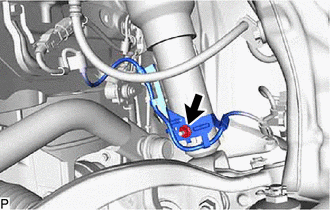
CONNECT NO.4 HEIGHT CONTROL TUBE
-
Connect the No. 4 height control tube to the front pneumatic cylinder with shock absorber assembly LH.
-
-
CONNECT STEERING KNUCKLE ASSEMBLY LH
-
CONNECT DISC BRAKE CYLINDER ASSEMBLY LH
-
CONNECT FRONT SKID CONTROL SENSOR WIRE LH
-
Install the front skid control sensor wire LH with the nut.
- Torque:
- 8.5 N*m { 87 kgf*cm, 75 in.*lbf }
-
-
CONNECT FRONT HEIGHT CONTROL SENSOR SUB-ASSEMBLY LH
-
Install the front height control sensor sub-assembly LH with the bolt.
- Torque:
- 5.4 N*m { 55 kgf*cm, 48 in.*lbf }
-
-
CONNECT FRONT STABILIZER LINK ASSEMBLY LH
-
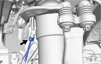
INSTALL ABSORBER CONTROL WIRE LH
-
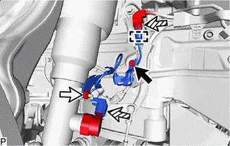
Bolt Nut 
Connector Connect the clamp and 2 connectors.
-
Install the absorber control wire LH with the bolt and nut.
- Torque:
- 8.5 N*m { 87 kgf*cm, 75 in.*lbf }
-
-
AIR MOVEMENT (WHEN REPLACING A FRONT PNEUMATIC CYLINDER)
-
AIR MOVEMENT (WHEN REPLACING THE 2 FRONT PNEUMATIC CYLINDERS)
-
STABILIZE SUSPENSION
-
Install the front wheel.
-
Lower the vehicle and bounce it up and down several times to stabilize the front suspension.
-
Remove the front wheel.
-
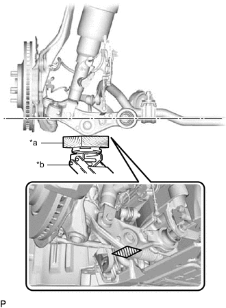
*a Wooden Block *b Jack Jack up the front lower suspension arm assembly, and place a wooden block under it to avoid damage. Apply load to the suspension so that the front lower suspension arm assembly is placed in a horizontal position.
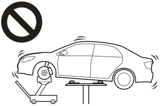
CAUTION:
-
Do not raise the jack up too high.
-
The vehicle could fall, resulting in a serious accident.
Note
-
When jacking up the front lower suspension arm assembly, be sure to jack it up slowly.
-
Make sure to perform this operation with the vehicle kept as low as possible.
-
-
-
FULLY TIGHTEN FRONT PNEUMATIC CYLINDER WITH SHOCK ABSORBER ASSEMBLY LH
-
Install the front pneumatic cylinder with shock absorber assembly LH (upper side) with the 3 nuts.
- Torque:
- 44 N*m { 449 kgf*cm, 32 ft.*lbf }
-
Fully tighten the front pneumatic cylinder with shock absorber assembly LH bolt.
- Torque:
- 110 N*m { 1122 kgf*cm, 81 ft.*lbf }
Note
Because the nut has its own stopper, do not turn the nut. Tighten the bolt with the nut secured.
-
-
INSTALL FRONT SHOCK ABSORBER CAP LH
-
INSTALL FRONT WHEEL
-
INSTALL UPPER RADIATOR SUPPORT SEAL (for LH Side)
-
INSTALL RADIATOR COVER PLATE (for RH Side)
-
CHECK CONNECTIONS OF TUBES FOR AIR LEAKAGE
-
INSPECT AND ADJUST FRONT WHEEL ALIGNMENT
-
INSPECT AND ADJUST VEHICLE HEIGHT
-
CHECK HEIGHT CHANGE OPERATION
-
PERFORM INITIALIZATION
Parking support brake system Panoramic view monitor system Parking assist monitor system -
ADJUST HEADLIGHT AIMING