ECD SYSTEM (w/ EGR Cooler), Diagnostic DTC:P0489, P0490
| DTC Code | DTC Name |
|---|---|
| P0489 | Exhaust Gas Recirculation Control Circuit Low |
| P0490 | Exhaust Gas Recirculation Control Circuit High |
DESCRIPTION
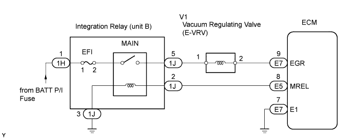
The EGR system recirculates exhaust gases, in order to suit every driving condition. The recirculated gas mingles with intake air, therefore the EGR system can slow combustion speed and keep the combustion temperature down. This helps reduce NOx emission.
In order to increase EGR circulation efficiency, the ECM adjusts the lift amount of the EGR valve and throttle valve angle.
| DTC No. | DTC Detection Condition | Trouble Area |
|---|---|---|
| P0489 | Open or short in E-VRV circuit for 5 seconds or more (1 trip detection logic) |
|
| P0490 | Open or short in E-VRV circuit for 5 seconds or more (1 trip detection logic) |
|
WIRING DIAGRAM
INSPECTION PROCEDURE
Note
After replacing the ECM, the new ECM needs registration Click here and initialization Click here.
PROCEDURE
-
INSPECT VACUUM REGULATING VALVE (E-VRV)
-
Inspect the vacuum regulating valve (E-VRV) Click here.
NG 
REPLACE VACUUM REGULATING VALVE (E-VRV) Click here
OK 
-
-
INSPECT VACUUM REGULATING VALVE (E-VRV) (POWER SOURCE VOLTAGE)
-
Disconnect the V1 vacuum regulating valve (E-VRV) connector.
-
Turn the ignition switch ON.
-
Measure the voltage of the wire harness side connector and body ground.
Standard voltage Tester Connection Specified Condition V1-1 - Body ground 11 to 14 V
NG 
CHECK HARNESS AND CONNECTOR (VACUUM REGULATING VALVE (E-VRV) - INTEGRATION RELAY) Click here
OK
-
-
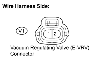
CHECK HARNESS AND CONNECTOR (VACUUM REGULATING VALVE (E-VRV) - ECM)
-
Disconnect the V1 vacuum regulating valve (E-VRV) connector.
-
Disconnect the E7 ECM connector.
-
Measure the resistance of the wire harness side connector.
Standard resistance (Check for open) Tester Connection Specified Condition V1-2 - EGR (E7-9) Below 1 Ω Standard resistance (Check for short) Tester Connection Specified Condition V1-2 or EGR (E7-9) - Body ground 10 kΩ or higher
NG
REPAIR OR REPLACE HARNESS AND CONNECTOR
OK 
REPLACE ECM Click here
-
-
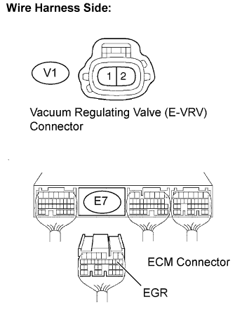
CHECK HARNESS AND CONNECTOR (VACUUM REGULATING VALVE (E-VRV) - INTEGRATION RELAY)
-
Remove the integration relay from the engine room junction block Click here.
-
Disconnect the 1J integration relay connector.
-
Disconnect the V1 vacuum regulating valve (E-VRV) connector.
-
Measure the resistance of the wire harness side connectors.
Standard resistance (Check for open) Tester Connection Specified Condition 1J-5 - V1-1 Below 1 Ω Standard resistance (Check for short) Tester Connection Specified Condition 1J-5 - V1-1 Below 1 Ω 1J-5 or V1-1 - Body ground 10 kΩ or higher
NG
REPAIR OR REPLACE HARNESS AND CONNECTOR
OK
INSPECT ECM POWER SOURCE CIRCUIT Click here
-