AUTOMATIC TRANSMISSION SYSTEM, Diagnostic DTC:P0982, P0983

| DTC Code | DTC Name |
|---|---|
| P0982 | Shift Solenoid "D" Control Circuit Low (Shift Solenoid Valve S4) |
| P0983 | Shift Solenoid "D" Control Circuit High (Shift Solenoid Valve S4) |
DESCRIPTION
Based upon a signal from the TCM, the combination of shift solenoid valve (S1, S2, S3, S4, SR, SL1, SL2) changes the gear position from 1st to 6th. As a fail-safe function if the solenoid valve system is open or shorted, the TCM cuts power to all solenoids, leaving just the mechanical hydraulic circuit, requiring manual shifting.
| DTC No. | DTC Detection Condition
|
Trouble Area |
|---|---|---|
| P0982 |
|
|
| P0983 |
|
|
MONITOR DESCRIPTION
These DTCs indicate an open or short in the shift solenoid valve S4 circuit. When there is an open or short circuit in any shift solenoid valve circuit, the TCM detects the problem and illuminates the MIL and stores the DTC.
WIRING DIAGRAM
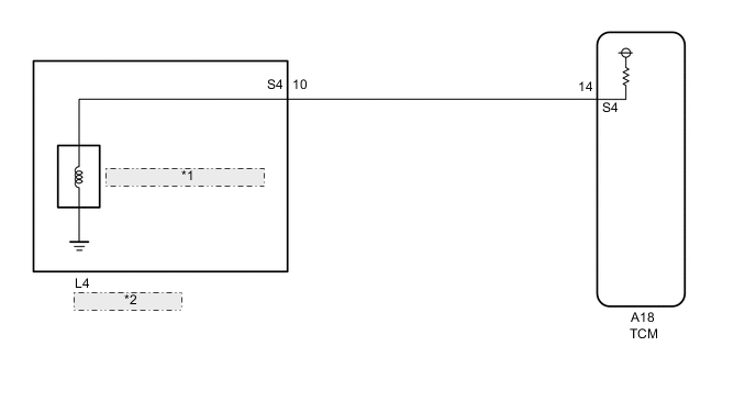
| *1 | Shift Solenoid Valve S4 |
| *2 | Transmission Wire |
CAUTION / NOTICE / HINT
Note
Perform the universal trip to clear permanent DTCs Click here.
Tech Tips
-
The shift solenoid valve S4 is turned on/off normally when the shift lever is in the D position:
TCM command gearshift 1st 2nd 3rd 4th 5th 6th Shift solenoid valve S4 OFF ON OFF OFF ON ON
PROCEDURE
-
INSPECT TRANSMISSION WIRE (S4)
-
Disconnect the A18 TCM connector.
-
Measure the voltage according to the value(s) in the table below.
Standard voltage Tester Connection Condition Specified Condition A18-14(S4) - Body ground Ignition switch ON Below 1 V -
Measure the resistance according to the value(s) in the table below.
Standard resistance Tester Connection Condition Specified Condition A18-14(S4) - Body ground 20°C(68°F) 11 to 15 Ω -
Connect the A18 TCM connector.
NG 
CHECK HARNESS AND CONNECTOR (TRANSMISSION WIRE - TCM) Click here
OK 
-
-
REPLACE TCM
-
Replace the TCM Click here.
NEXT 
PERFORM THE RESET MEMORY Click here
-
-
CHECK HARNESS AND CONNECTOR (TRANSMISSION WIRE - TCM)
-
Disconnect the A18 TCM connector.
-
Disconnect the L4 transmission wire connector.
-
Measure the voltage according to the value(s) in the table below.
Standard voltage Tester Connection Condition Specified Condition L4-10(S4) - Body ground Ignition switch ON Below 1 V -
Measure the resistance according to the value(s) in the table below.
Standard resistance Tester Connection Condition Specified Condition L4-10(S4) - A18-14(S4) Always Below 1 Ω L4-10(S4) and A18-14(S4) - Body ground Always 10 kΩ or higher -
Connect the A18 TCM connector.
-
Connect the L4 transmission wire connector.
NG
REPAIR OR REPLACE HARNESS OR CONNECTOR
OK
-
-
INSPECT SHIFT SOLENOID VALVE S4
-
Remove the shift solenoid valve S4 Click here.
-
Perform inspection of the shift solenoid valve S4 Click here.
OK
REPAIR OR REPLACE TRANSMISSION WIRE Click here
NG
REPLACE SHIFT SOLENOID VALVE S4 Click here
-