KICK SENSOR REMOVAL
CAUTION / NOTICE / HINT
The necessary procedures (adjustment, calibration, initialization, or registration) that must be performed after parts are removed, installed, or replaced during the kick door control sensor removal/installation are shown below.
| Replacement Part | Necessary Procedure | Effect/Inoperative Function When Necessary Procedures are not Performed | Link |
|---|---|---|---|
| Removal and installation of battery terminal | Drive the vehicle until stop and start control is permitted (approximately 5 to 60 minutes) | Stop and start system | |
| Memorize steering angle neutral point | LKA/LDA system | ||
| Parking support brake system* | |||
| Pre-collision system | |||
| Adaptive high beam system | |||
Lighting system (EXT) |
|||
| Variable gear ratio steering system | |||
| Parking assist monitor system | |||
| Panoramic view monitor system | |||
| Initialize Rear Door Sunshade System | Rear door sunshade system | ||
| Initialize power trunk lid system | Power trunk lid system | ||
| Rear bumper assembly (Including removal and installation) |
|
Parking support brake system | |
| Kick door control sensor | Reset connection history | There are cases where the connection history display differs from the vehicle condition |
Click here Click here
PROCEDURE
-
PRECAUTION
Note
After turning the engine switch off, waiting time may be required before disconnecting the cable from the negative (-) battery terminal. Therefore, make sure to read the disconnecting the cable from the negative (-) battery terminal notices before proceeding with work.
-
REMOVE LUGGAGE COMPARTMENT MAT SUB-ASSEMBLY
-
DISCONNECT CABLE FROM NEGATIVE BATTERY TERMINAL
-
REMOVE REAR BUMPER COVER
-
REMOVE KICK DOOR CONTROL BRACKET
-
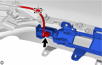
Disconnect the connector and detach the wire harness clamp.
Note
Do not touch the terminal of the kick door control sensor connector.
-
Remove the 3 screws.
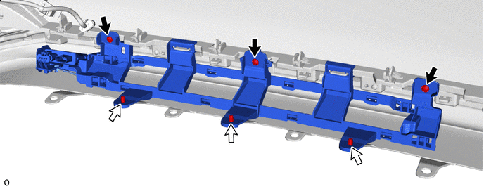

Screw 
Clip -
Remove the 3 clips.
-
Detach the claw and remove the kick door control bracket together with the kick door control sensor as shown in the illustration.
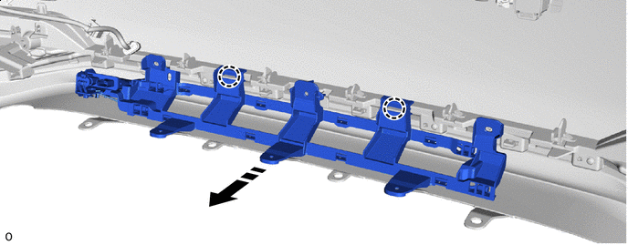

Remove in this Direction - -
-
-
REMOVE KICK DOOR CONTROL SENSOR
-
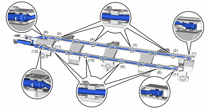
Detach the claw and guide and disconnect the antenna cable in the order shown in the illustration.
-
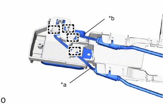
*a Red Wire *b Black Wire Detach the clamp and disconnect the red wire and black wire from the kick door control bracket.
Note
-
Do not pull strongly on the wire.
-
Do not twist the wire.
-
-
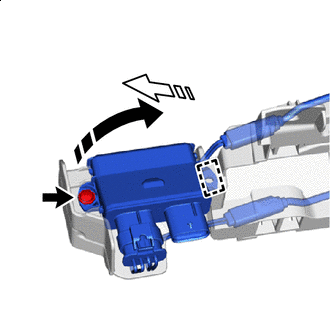
Remove in this Direction (1) 
Remove in this Direction (2) Remove the screw.
-
Detach the guide and remove the kick door control sensor from the kick door control bracket in the direction indicated by the arrow shown in the illustration.
Note
-
Do not subject the kick door control sensor to strong impacts or force, and do not drop it.
-
Do not reuse a kick door control sensor which has been subjected to an impact or dropped.
-
-