INTAKE MANIFOLD INSTALLATION
-
INSTALL INTAKE MANIFOLD
-
w/o EGR Cooler:
-
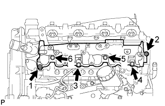
Temporarily install a new gasket and the intake manifold with the 4 bolts and 2 nuts.
-
Tighten the 4 bolts and 2 nuts in the order shown in the illustration.
-
-
w/ EGR Cooler:
-
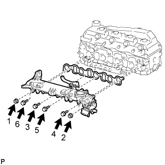
Temporarily install a new gasket and the manifold with the 2 nuts and 4 bolts.
-
Tighten the 2 nuts and 4 bolts in the order shown in the illustration.
- Torque:
- 29 N*m { 296 kgf*cm, 21 ft.*lbf }
Note
-
-
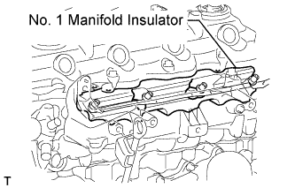
When installing the intake manifold, make sure that the No. 1 manifold insulator is not pinched.
-
Make sure that the swirl control valve actuator is not damaged by surrounding parts.
-
Tighten the 2 nuts and 4 bolts in the order shown in the illustration.
-
Connect the vacuum hose and connector to the vacuum switching valve.
-
-
-
INSTALL INTAKE MANIFOLD INSULATOR (w/ EGR Cooler)
-
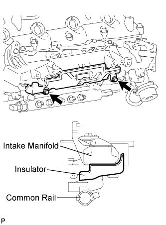
Install the insulator with the 2 bolts.
- Torque:
- 8.0 N*m { 82 kgf*cm, 71 in.*lbf }
-
-
INSTALL NO. 3 INTERCOOLER SUPPORT BRACKET (w/ EGR Cooler)
-
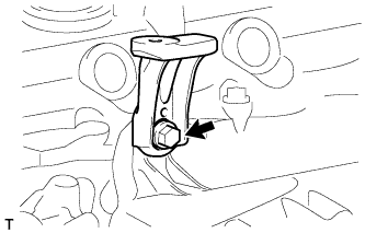
Install the support bracket with the bolt.
- Torque:
- 23 N*m { 235 kgf*cm, 17 ft.*lbf }
-
-
INSTALL NO. 2 NOZZLE LEAKAGE PIPE ASSEMBLY (w/o EGR Cooler)
-
Temporarily install the No. 2 nozzle leakage pipe with the 3 bolts.
-
Temporarily install a new gasket and the union bolt.
-
Tighten the 3 bolts and union bolt.
- Torque:
- for bolt
- 13 N*m { 130 kgf*cm, 9 ft.*lbf }
- for union bolt
- 21 N*m { 214 kgf*cm, 15 ft.*lbf }
-
Connect the 3 fuel hoses.
-
-
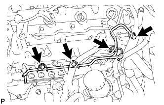
INSTALL NO. 2 NOZZLE LEAKAGE PIPE ASSEMBLY (w/ EGR Cooler)
-
Temporarily install the leakage pipe with the 3 bolts.
-
Temporarily install a new gasket with the check valve.
-
Tighten the 3 bolts and check valve.
- Torque:
- for check valve
- 21 N*m { 214 kgf*cm, 15 ft.*lbf }
- for bolt
- 13 N*m { 130 kgf*cm, 9 ft.*lbf }
-
Connect the 3 fuel hoses.
-
-
INSTALL NO. 4 INJECTION PIPE SUB-ASSEMBLY (w/o EGR Cooler)
-
Temporarily install the No. 4 injection pipe with the union nuts.
-
Install the 2 bolts.
- Torque:
- 13 N*m { 130 kgf*cm, 9 ft.*lbf }
Note
-
If an injection pipe clamp is removed from the No. 4 injection pipe, replace the injection clamp with a new one.
-
Make sure that the inner-rubbers of the injection pipe fit inside the clamps.
-
When installing the pipe, check that the inner-rubbers and the clamps are in their proper positions.
-
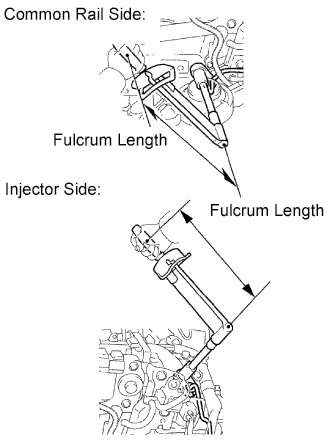
Using a 17 mm union nut wrench, tighten the injection pipe union nut on the common rail side.
- Torque:
- 35 N*m { 357 kgf*cm, 26 in.*lbf }
Note
Use the formula to calculate special torque values for situations where a union nut wrench is combined with a torque wrench Click here.
-
Using a 17 mm union nut wrench, tighten the injection pipe union nut on the injector side.
- Torque:
- 35 N*m { 357 kgf*cm, 26 in.*lbf }
Note
Use the formula to calculate special torque values for situations where a union nut wrench is combined with a torque wrench Click here.
-
-
INSTALL NO. 4 INJECTION PIPE SUB-ASSEMBLY (w/ EGR Cooler)
Note
-
When replacing an injector, it is necessary to replace the 4 injection pipes with new ones.
-
Keep the joints of the injection pipe clean.
-
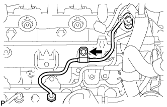
Temporarily install the No. 4 injection pipe with the union nuts.
-
Install the bolt.
- Torque:
- 5.0 N*m { 51 kgf*cm, 44 in.*lbf }
Note
-
If an injection pipe clamp is removed from the No. 4 injection pipe, replace the injection clamp with a new one.
-
Make sure that the inner-rubbers of the injection pipe fit inside the clamp.
-
When installing the pipe, check that the inner rubbers and the clamp are in their proper positions.
-
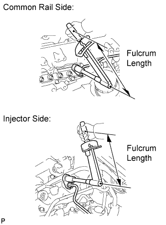
Using a 17 mm union nut wrench, tighten the injection pipe union nuts on the common rail side.
- Torque:
- 35 N*m { 357 kgf*cm, 26 ft.*lbf }
Note
Use the formula to calculate special torque values for situations where a union nut wrench is combined with a torque wrench Click here.
-
Using a union nut wrench, tighten the injection pipe union nuts on the injector side.
- Torque:
- 35 N*m { 357 kgf*cm, 26 ft.*lbf }
Note
Use the formula to calculate special torque values for situations where a union nut wrench is combined with a torque wrench Click here.
-
-
INSTALL NO. 1, NO. 2 AND NO. 3 INJECTION PIPE SUB-ASSEMBLY (w/o EGR Cooler)
Note
-
When replacing an injector, it is necessary to replace the 4 injection pipes with new ones.
-
Keep the joints of the injection pipe clean.
-
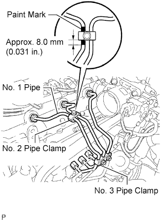
Temporarily install the No. 1, No. 2 and No. 3 injection pipes with the union nuts.
-
Install the No. 2 and No. 3 injection pipe clamps with the bolt and 2 nuts, as shown in the illustration.
- Torque:
- 5.0 N*m { 51 kgf*cm, 44 in.*lbf }
Tech Tips
If the painted mark on the No. 1 injection pipe has disappeared, use the illustration as a reference to install the clamps.
-
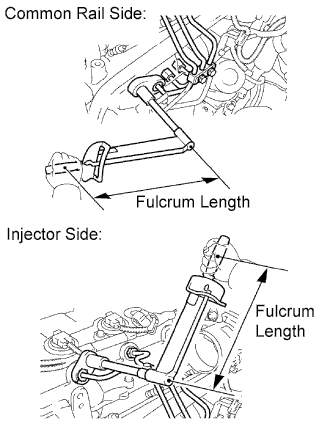
Using a 17 mm union nut wrench, tighten the injection pipe union nuts on the common rail side.
- Torque:
- 35 N*m { 357 kgf*cm, 26 in.*lbf }
Note
Use the formula to calculate special torque values for situations where a union nut wrench is combined with a torque wrench Click here.
-
Using a 17 mm union nut wrench, tighten the injection pipe union nuts on the injector side.
- Torque:
- 35 N*m { 357 kgf*cm, 26 in.*lbf }
Note
Use the formula to calculate special torque values for situations where a union nut wrench is combined with a torque wrench Click here.
-
-
INSTALL EGR VALVE ASSEMBLY (w/ EGR System without EGR Cooler)
-
Install a new gasket and the EGR valve.
-
-
INSTALL NO. 1 EGR PIPE SUB-ASSEMBLY (w/ EGR System without EGR Cooler)
-
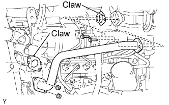
Install 2 new gaskets and the pipe with the 2 nuts and 2 bolts.
- Torque:
- 13 N*m { 133 kgf*cm, 10 ft.*lbf }
Tech Tips
The gasket's claws should be on the pipe side.
-
-
INSTALL INTAKE AIR CONNECTOR (w/o EGR Cooler)
-
Remove the 2 nuts, bolt, air connector and gasket.
-
-
INSTALL THROTTLE BODY BRACKET (w/o EGR Cooler)
-
Install the bracket with the 3 bolts.
- Torque:
- 20 N*m { 204 kgf*cm, 15 ft.*lbf }
-
-
INSTALL VACUUM SWITCHING VALVE BRACKET
-
w/o EGR System:
-
Install the vacuum switching valve bracket with the 2 bolts.
- Torque:
- 20 N*m { 204 kgf*cm, 15 ft.*lbf }
-
-
w/ EGR System without EGR Cooler:
-
Install the bracket with the 2 bolts.
- Torque:
- 20 N*m { 204 kgf*cm, 15 ft.*lbf }
-
Connect the vacuum hoses to the 2 locations and 2 connectors.
-
-
-
INSTALL EGR COOLER
-
INSTALL ENGINE OIL LEVEL DIPSTICK GUIDE
-
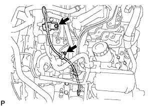
Install a new O-ring to the engine oil level dipstick guide.
-
Apply a small amount of clean engine oil to the O-ring.
-
Install the engine oil level dipstick guide with the bolt.
- Torque:
- 8.0 N*m { 82 kgf*cm, 71 in.*lbf }
-
Install the injection pipe clamp with the bolt.
- Torque:
- 5.0 N*m { 51 kgf*cm, 44 in.*lbf }
-
-
INSTALL MANIFOLD STAY
-
w/o EGR Cooler:
-
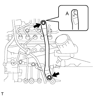
Install the stay with the 2 bolts.
- Torque:
- 19 N*m { 194 kgf*cm, 14 ft.*lbf }
Tech Tips
The manifold stay indented area (labeled A) must face the manifold.
-
-
w/ EGR Cooler:
-
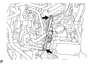
Install the manifold with the 2 bolts.
- Torque:
- 19 N*m { 194 kgf*cm, 14 ft.*lbf }
-
Connect the 3 vacuum hoses and 2 VSV connectors.
-
-
-
INSTALL DIESEL THROTTLE BODY ASSEMBLY (w/o EGR Cooler)
-
BLEED AIR FROM FUEL SYSTEM
-
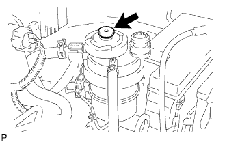
Using the hand pump mounted on the fuel filter cap, bleed the air from the fuel system. Continue pumping until the pump resistance increases.
Note
-
Hand pump pumping speed: Max. 2 strokes/ sec.
-
The hand pump must be pushed with a full stroke during pumping.
-
When the fuel pressure at the supply pump inlet port reaches a saturated pressure, the hand pump resistance increases.
-
If pumping is interrupted during the air bleeding process, fuel in the fuel line may return to the fuel tank. Continue pumping until the hand pump resistance increases.
-
If the hand pump resistance does not increase despite consecutively pumping 200 times or more, there may be a fuel leak between the fuel tank and fuel filter, the hand pump may be malfunctioning, or the vehicle may have run out of fuel.
-
If air bleeding using the hand pump is incomplete, the common rail pressure does not rise to the pressure range necessary for normal use, and the engine cannot be started.
-
-
Start the engine.
Note
-
Even if air bleeding using the hand pump has been completed, the starter may need to be cranked for 10 seconds or more to start the engine.
-
Do not crank the engine continuously for more than 20 seconds. The battery may be discharged.
-
Use a fully-charged battery.
-
When the engine can be started, proceed to the next step.
-
If the engine cannot be started, bleed the air again using the hand pump until the hand pump resistance increases (refer to the procedures above). Then start the engine.
-
-
Turn the ignition switch off.
-
Connect the intelligent tester to the DLC3.
-
Turn the ignition switch to ON and turn the intelligent tester on.
-
Clear the DTCs Click here.
-
Start the engine.*1
-
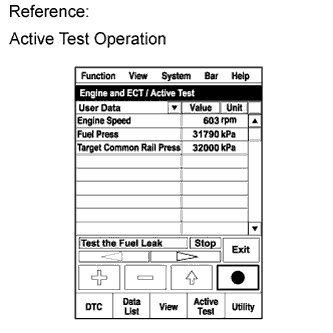
Enter the following menus: Powertrain / Engine and ECT / Active Test / Test the Fuel Leak.*2
-
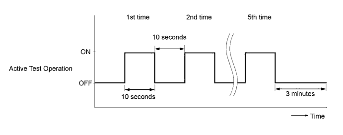
Perform the following test 5 times with on/off intervals of 10 seconds: Active Test / Test the Fuel Leak.*3
-
Allow the engine to idle for 3 minutes or more after performing the Active Test for the fifth time.
Tech Tips
When the Active Test "Test the Fuel Leak" is used to change the pump control mode, the actual fuel pressure inside the common rail drops below the target fuel pressure when the Active Test is off, but this is normal and does not indicate a pump malfunction.
-
Enter the following menus: Powertrain / Engine and ECT / DTC.
-
Read Current DTCs.
-
Clear the DTCs Click here.
Tech Tips
It is necessary to clear the DTCs as DTC P1604 or P1605 may be stored when air is bled from the fuel system after replacing or repairing fuel system parts.
-
Repeat steps *1 to *3.
-
Enter the following menus: Powertrain / Engine and ECT / DTC.
-
Read Current DTCs.
OK No DTCs are output.
-
-
CONNECT CABLE TO NEGATIVE BATTERY TERMINAL
-
CHECK FOR FUEL LEAKS
CAUTION:
-
During Active Test mode, engine speed becomes high and combustion noise becomes loud, so pay attention.
-
During Active Test mode, fuel becomes high-pressured. Be extremely careful not to expose your eyes, hands, or body to escaped fuel.
-
Check that there are no leaks from any part of the fuel system when the engine is stopped. If there is fuel leakage, repair or replace parts as necessary.
-
Start the engine and check that there are no leaks from any part of the fuel system. If there is fuel leakage, repair or replace parts as necessary.
-
Disconnect the return hose from the common rail.
-
Start the engine and check for fuel leaks from the return pipe.
If there is fuel leakage, replace the common rail.
-
Connect the intelligent tester to the DLC3.
-
Start the engine and push the intelligent tester main switch on.
-
Select the Fuel Leak test from the Active Test mode on the intelligent tester.
-
If the intelligent tester is not available, fully depress the accelerator pedal quickly. Increase the engine speed to the maximum and maintain that speed for 2 seconds. Repeat this operation several times.
-
Check that there are no leaks from any part of the fuel system.
Note
A return pipe leakage of less than 10 cc (0.6 cu in.) per minute is acceptable.
If there is fuel leakage, repair or replace parts as necessary.
-
Reconnect the return hose to the common rail.
-
-
PERFORM INITIALIZATION
-
Perform initialization Click here.
Note
Certain systems need to be initialized after disconnecting and reconnecting the cable from the negative (-) battery terminal.
-